
- Catalogs
- Imao Corporation
- PNEUMATIC CLAMPS

PNEUMATIC CLAMPS
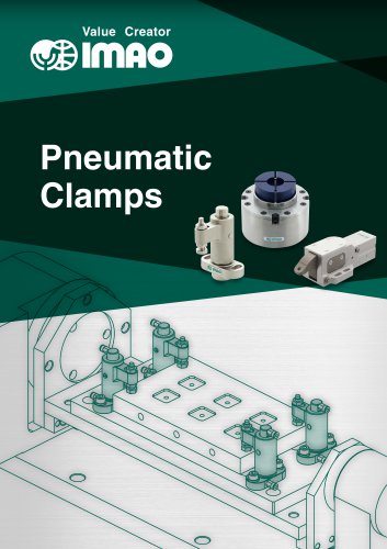
PNEUMATIC CLAMPS
IMAO's Air Assisted Clamps are designed to enhance efficiency and automation in production processes by combining mechanical and pneumatic technologies. These clamps offer a compact and efficient solution for automated clamping needs.
- Work-friendly: Automation of clamping and unclamping processes increases work efficiency, allowing for simultaneous controls and remote operations.
- Design-friendly: The unitized design reduces the need for multiple components, resulting in a compact and efficient fixture design.
The lineup includes various pneumatic clamps such as Compact Pneumatic Swing Clamps, Pneumatic OD Holding Clamps, Pneumatic Pull Clamps, Pneumatic Work Supports, and Pneumatic Flex Locators. These are ideal for handling irregular-shaped or small workpieces and allow for multi-surface machining.
Specifications include material composition (e.g., SCM440 steel, S45C steel), operating air pressure range (0.5 to 0.7 MPa), clamping force, holding capacity, dimensions, and mounting-hole specifications.
Applications include vertical machining centers with NC rotary tables, 5-axis machining centers, and assembling lines. The wedge mechanism allows for stable clamping force and accurate machining from multiple sides.
Instructions include ensuring proper clearance between the clamping spindle and workpiece, using clean air to prevent malfunctions, and adjusting the clamping spindle using a feeler gauge.
IMAO's Air Assisted Clamps offer a versatile and efficient solution for automated clamping needs, focusing on compact design and enhanced productivity.
- Materials: Made from SCM440 steel, A5056 aluminum, and S45C steel, with finishes like electroless nickel plating and anodizing for durability.
- Design Features: Compact design with detecting ports for clamping and unclamping, some models include a wedge mechanism to enhance clamping force.
- Operating Conditions: Operate at air pressures ranging from 0.3 to 1.0 MPa, with clamping forces varying by model.
- Installation: Attach collars and retaining rings manually, ensuring proper alignment and clearance.
- Connection: Pressure sensors are required for monitoring clamping conditions, with proper piping connections to designated ports.
- Maintenance: Use clean air, free from moisture and debris, to prevent malfunctions. Regular checks for air leaks and proper sealing are recommended.
- Clamping Force: The wedge mechanism provides up to 150% increased clamping force, maintaining effectiveness even if air pressure drops.
- Sensor Integration: Magnetic sensors can be mounted to detect clamping conditions, with specific models tested for compatibility.
- Adjustments: Clamping height and stroke can be adjusted within specified ranges to accommodate different workpiece sizes.
- Ensure all components are correctly installed and adjusted before use.
- Regularly inspect and maintain the air supply system to ensure optimal performance.
- Consider environmental factors such as vibration, which may affect clamping force.
Catalog excerpts

Pneumatic Clamps
Open the catalog to page 1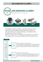
AIR ASSISTED CLAMPS [Mechanical + Air = Hybrid] AIR ASSISTED CLAMPS are IMAO's automated clamps that satisfy needs for much more efficiency and automation in production. Our original mechanical clamp technology in combination with air provides diverse lineup of products. With our own know-how as a clamping tools manufacturer, we unitized the clamping devices to support making compact automated fixtures. Provide 2 advantages with Mechanical + Air Mechanism Greater efficiency by automation. Pneumatic clamping and unclamping improves work efficiency compared to manual operations. Simultaneous controls...
Open the catalog to page 2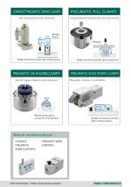
COMPACT PNEUMATIC SWING CLAMPS PNEUMATIC PULL CLAMPS High clamping force with small body Clamping workpiece with through hole allows multi-surface machining. Wedge Piston Workpiece Wedge mechanism provides high holding capacity. Wedge mechanism provides high clamping force. PNEUMATIC OD HOLDING CLAMPS PNEUMATIC HOLD DOWN CLAMPS Ideal for irregular-shaped or small workpieces. Machine the jaw to custom fit a workpiece. Magnetic sensor mountable. Wedge mechanism provides high holding capacity. More air-assisted products! COMPACT PNEUMATIC WORK SUPPORTS PNEUMATIC WORK SUPPORTS PNEUMATIC FLEX LOCATORS...
Open the catalog to page 3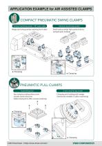
APPLICATION EXAMPLE for AIR ASSISTED CLAMPS COMPACT PNEUMATIC SWING CLAMPS Vertical machining center + NC rotary table Wedge style locking provides machining from 4 sides! Vertical machining center Small body provides high productivity by multiple-parts holding! PNEUMATIC PULL CLAMPS Assembling line Easy workpiece loading without screw provides shorter setup time. Stable clamping force offers accurate machining! 5-axis machining center Clamping and holding with wedge mechanism enables 5-sides machining!
Open the catalog to page 4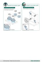
PNEUMATIC OD HOLDING CLAMPS Vertical machining center Machinable jaws allow clamping workpieces of various shapes to boost productivity. PNEUMATIC HOLD DOWN CLAMPS Horizontal machining center Less tool interference by low profile body!
Open the catalog to page 5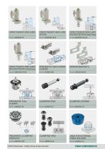
COMPACT PNEUMATIC SWING CLAMPS COMPACT PNEUMATIC SWING CLAMPS WITH ROD COMPACT PNEUMATIC SWING CLAMPS WITH DETECTING PORTS (Gasket Piping) COMPACT PNEUMATIC SWING CLAMPS WITH DETECTING PORTS (Thread Piping) PNEUMATIC HOLD DOWN CLAMPS SENSOR BRACKETS PNEUMATIC PULL CLAMPS CLAMPING PINS CLAMPING SCREWS PNEUMATIC CLAMPING MODULES CLAMPING PINS JAWS FOR EXTERNAL FORM HOLDING
Open the catalog to page 6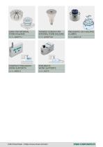
JAWS FOR INTERNAL FORM HOLDING TAPERED SCREWS FOR INTERNAL FORM HOLDING PNEUMATIC OD HOLDING CLAMPS COMPACT PNEUMATIC WORK SUPPORTS PNEUMATIC WORK SUPPORTS
Open the catalog to page 7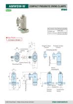
CSI3 COMPACT PNEUMATIC SWING CLAMPS [ Compact design! Body / Clamp Arm / Piston Rough Surface Contact Finished Surface Contact Unclamping Port Clockwise Counterclockwise Clamping Clamping
Open the catalog to page 8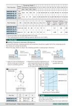
*) Clamping height can be adjusted within this range. **) The clamping force and the holding capacity above are at 0.5 MPa. Performance Curve Part No. ■ Use clean air by removing moisture and debris with an air dryer and air filter. ■ Impurities in the compressed air can cause malfunction. imflo corporator
Open the catalog to page 9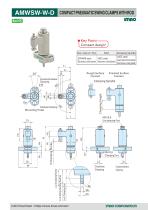
COMPACT PNEUMATIC SWING CLAMPS WITH ROD ★ Key Point- Compact design! Body / Clamp Arm / Piston Rough Surface Finished Surface Contact Contact Clamping Spindle
Open the catalog to page 10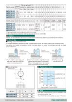
*) Clamping height can be adjusted within this range. **) The clamping force and the holding capacity above are at 0.5 MPa. The rod on the bottom of the clamp can be used for detecting clamping/unclamping with switches. A clearance between clamping spindle and workpiece should be roughly half of the clamping stroke. The clamp arm swings horizontally. Follow the steps below to adjust the clamping spindle to create proper clearance. 1. Apply air to the unclamping port with an air blow gun to move the clamp to unclamping position. 2. Rotate the arm manually to straight direction, and 3. Fix the...
Open the catalog to page 11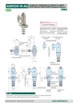
COMPACT PNEUMATIC SWING CLAMPS WITH DETECTING PORTS (Gasket Piping) ★Key Point Compact design! Body / Clamp Arm/ Piston Clamping Spindle S45C steel SCM440 steel A5056 aluminum Quenched and tempered Electroless nickel plated Anodized Electroless nickel plated Rough Surface Contact Finished Surface Contact Clamping Spindle Clamping Height Clockwise Clamping Mounting Holes Detecting Port for Clamping Detecting Port for Unclamping Clockwise Clamping Note ・Use clean air by removing moisture and debris with an air dryer and air filter. ・Impurities in the compressed air can cause malfunction.
Open the catalog to page 12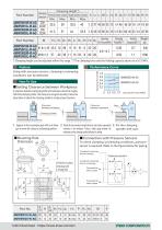
*) Clamping height can be adjusted within this range. **) The clamping force and the holding capacity above are at 0.5 MPa. Using with pressure sensors, clamping/unclamping conditions can be detected. A clearance between clamping spindle and workpiece should be roughly half of the clamping stroke. The clamp arm swings horizontally. Follow the steps below to adjust the clamping spindle to create proper clearance. 1. Apply air to the unclamping port with an air blow 2. Rotate the arm manually to straight direction, and create an appropriate 3. Fix the clamping gun to move the clamp to unclamping...
Open the catalog to page 13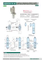
COMPACT PNEUMATIC SWING CLAMPS WITH DETECTING PORTS (Thread Piping)★ Key Point-Compact design! Body / Clamp Arm / Piston Clockwise Clamping Mounting Holes Rough Surface Finished Surface Contact Contact Clamping Spindle M5X0.8 Detecting Port for Clamping M5X08 Detecting Port for Unclamping ■Attach the collar and the retaining ring to the product by yourself. The collar rotates for 360°freely. Set the collar to your desired position. ■ Use clean air by removing moisture and debris with an air dryer and air filter. ■Impurities in the compressed air can cause malfunction. IfTlAO CORPORATOR
Open the catalog to page 14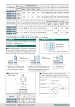
Part Number *) Clamping height can be adjusted within this range. **) The clamping force and the holding capacity above are at 0.5 MPa. Performance Curve Using with pressure sensors, clamping/unclamping conditions can be detected. A clearance between clamping spindle and workpiece should be roughly half of the clamping stroke.The clamp arm swings horizontally. Follow the steps below to adjust the clamping spindle to create proper clearance. 1. Apply air to the unclamping port with an air blow gun to move the clamp to unclamping position. 3. Fix the clamping spindle with nuts. 2. Rotate the arm...
Open the catalog to page 15All Imao Corporation catalogs and technical brochures
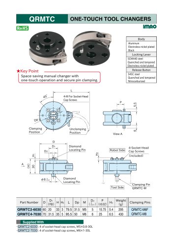 One-Touch Tool Changers
3 Pages
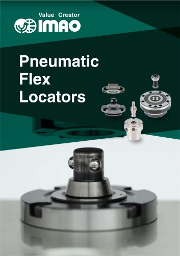 Pneumatic Flex Locators
24 Pages
 One Touch Fasteners
160 Pages
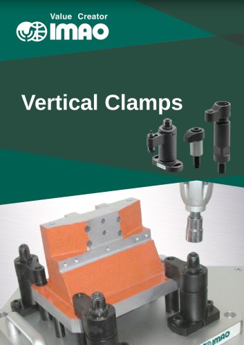 Vertical Clamps
20 Pages
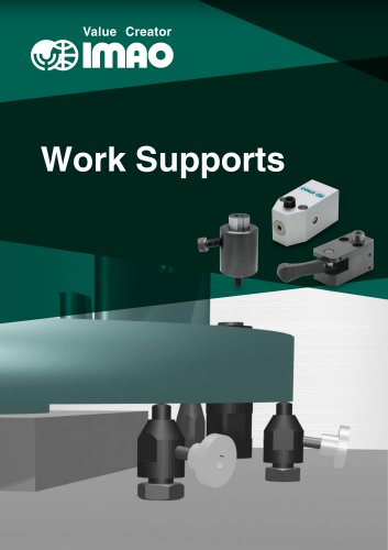 WORK SUPPORTS
31 Pages
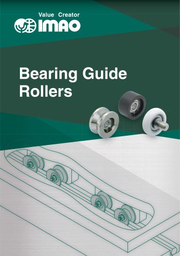 Bearing Guide Rollers
35 Pages
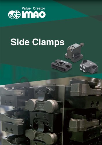 Side Clamps
27 Pages
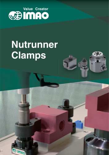 NUTRUNNER CLAMPS
24 Pages
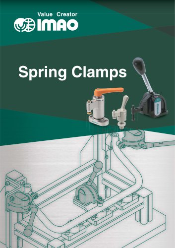 Spring Clamps
23 Pages
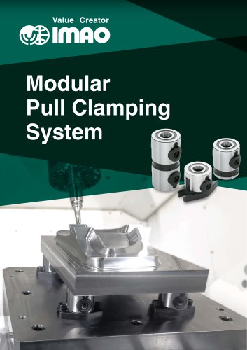 Modular Pull Clamping System
41 Pages
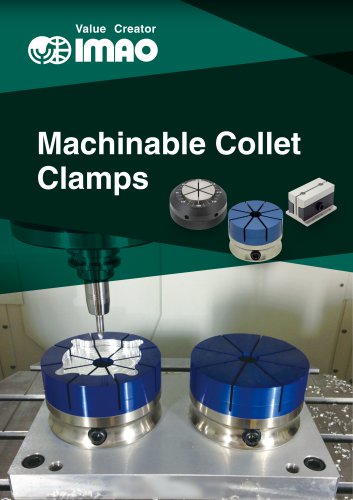 Machinable Collet Clamps
48 Pages
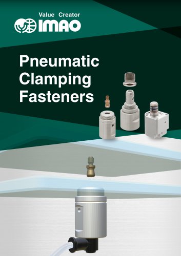 PNEUMATIC CLAMPING FASTENERS
16 Pages
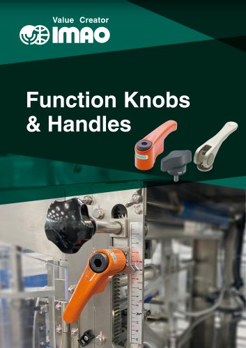 Function Knobs & Handles
22 Pages
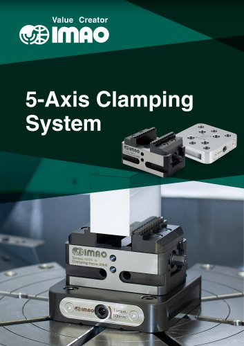 5-Axis Clamping Systems
15 Pages
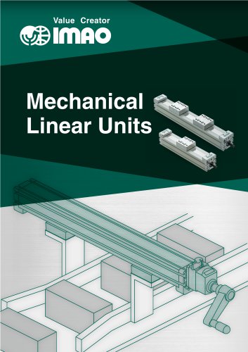 MECHANICAL LINEAR ACTUATORS
36 Pages
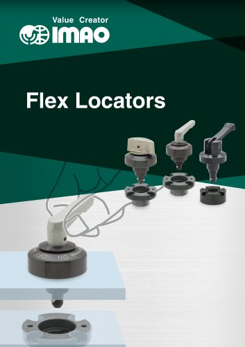 Flex Locators
46 Pages
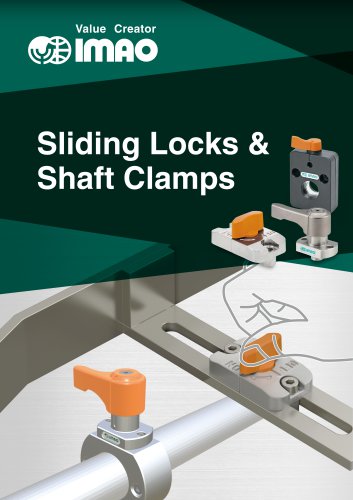 Sliding Locks & Shaft Clamps
59 Pages
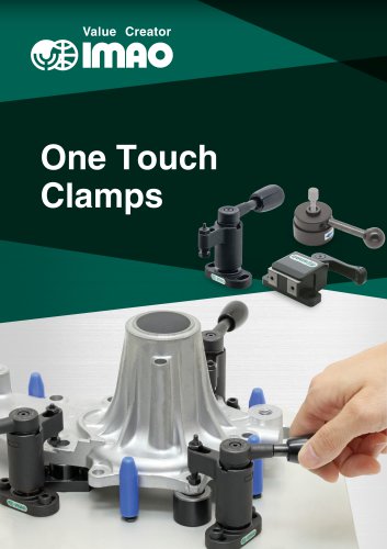 ONE TOUCH CLAMPS
68 Pages
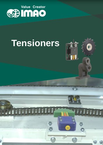 TENSIONERS
45 Pages
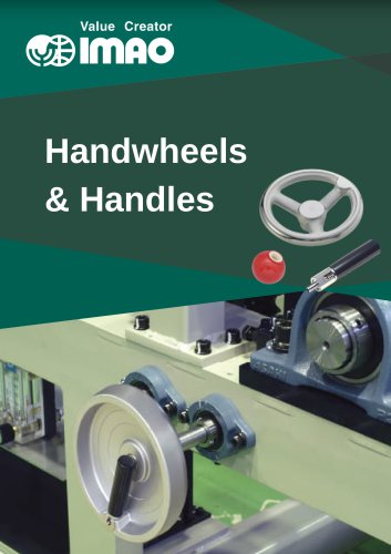 HANDWHEELS & HANDLES
31 Pages
 SCREWS & NUTS
13 Pages
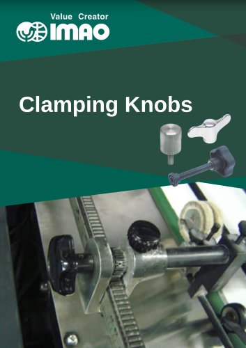 CLAMPING KNOBS
22 Pages
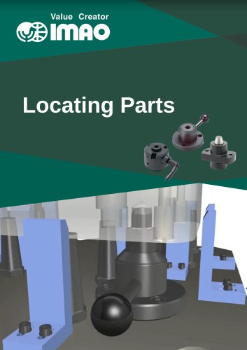 LOCATING PARTS
15 Pages
 GRIPPERS
28 Pages