- Catalogs
- Imao Corporation
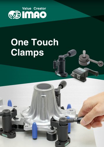
- ONE TOUCH CLAMPS
ONE TOUCH CLAMPS
1 /68Pages
ONE TOUCH CLAMPS
1 /68Pages
Catalog excerpts

Value Creator
Open the catalog to page 1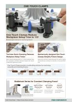
Manual quick clamps for machining fixture Pneumatic clamps Compared to Screwtightening clamps ^ Tool-less Quick Clamping Reduces Mechanically designed One-Touch Workpiece Setup Times! Clamps Simplify Fixture Design. Quick, tool-less clamping results in 1/3 of the workpiece setup time compared to old-style mechanical clamps that require cumbersome tightening of screws. Fixture with one-touch clamps eliminates the need for piping and maintenance, resulting in a reduction in the overall labor cost. One-Touch Clamps provide a workholding solution for machining, assembly and checking fixtures. Stablelock...
Open the catalog to page 2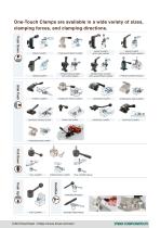
SWING CLAMPS WITH CAM HANDLE SWING CLAMPS WITH ADJUSTABLE HANDLE SWING CLAMPS RETRACTABLE CLAMPS WITH CAM HANDLE RETRACTABLE CLAMPS WITH ADJUSTABLE HANDLE THRUST CLAMPS LOW-PROFILE CAM EDGE CLAMPS PUSH CLAMPS
Open the catalog to page 3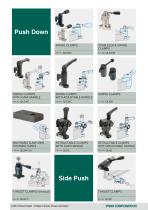
Push Down SWING CLAMPS STABLELOCK SWING CLAMPS SWING CLAMPS WITH CAM HANDLE SWING CLAMPS WITH ADJUSTABLE HANDLE SWING CLAMPS MACHINABLE CLAMP ARMS FOR SWING CLAMPS RETRACTABLE CLAMPS WITH CAM HANDLE RETRACTABLE CLAMPS WITH ADJUSTABLE HANDLE Side Push THRUST CLAMPS (Vertical) THRUST CLAMPS
Open the catalog to page 4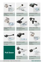
STABLELOCK THRUST CLAMPS CLAMPING BARS STABLELOCK SIDE CLAMPS LOW-PROFILE CAM EDGE CLAMPS STABLELOCK PUSH CLAMPS PULL CLAMPS CLAMPING PINS Pull Down
Open the catalog to page 5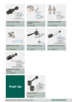
CLAMPING SCREWS STABLELOCK PULL CLAMPS CLAMPING SCREWS EXTENSION UNITS PULL CLAMPS (Heavy) CLAMPING PINS (Heavy) CLAMPING SCREWS (Heavy) Part No. QLPDH-M Push Up PUSH CLAMPS Part No. QLPU
Open the catalog to page 6
Value Creator
Open the catalog to page 7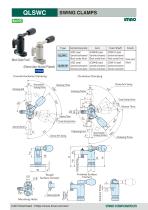
SWING CLAMPS (Electroless Nickel Plated) Type CAD Download : https://www.imao.com/en/ imnocoRPORATion
Open the catalog to page 8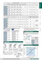
Technical Information Handles Push Up Pull Down Side Push ,, I, n Hex.Socket Head Cap Screw ■ How to Change Handle Position The dodecagonal socket in the hub of the handle allows changing the handle position by 30°. Dde^gml
Open the catalog to page 9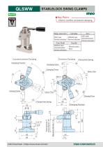
STABLELOCK SWING CLAMPS imno★Key Point ->.[ Click to confirm consistent clamping ^ Body, Lever Arm
Open the catalog to page 10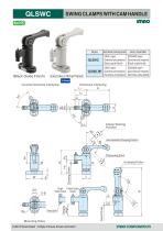
SWING CLAMPS WITH CAM HANDLE (Black Oxide Finish) (Electroless Nickel Plated) Style
Open the catalog to page 12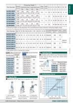
■Allowable Loads in Machining of Workpiece Bottom Ensure that any force more than stated below is not applied. Allowable Force To Workpiece Bottom (Per Clamp) Fixture Plate ■ Operation of CW Type (Invert the operation for CCW type.) 1. Unclamped 2. Arm Swing 3. Clamping Load or unlaod a Turn the handle to set the Set the handle down to workpiece. clamp arm in position. clamp the workpiece.
Open the catalog to page 13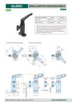
QLSWC SWING CLAMPS WITH ADJUSTABLE HANDLE Base/Washer/Clamping Spindle ■ Clamp worked by a screw-locking mechanism which allows providing longer clamping stroke and greater clamping force than a cam-locking mechanism. ■Operated by an adjustable handle that allows for flexible handle positioning. CAD Download : https://www.imao.com/en/ imnocoRPORRTion
Open the catalog to page 14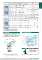
*) Clamping height can be adjusted. The parenthesised values denote clamping height range. Part Number ** ) Studs are bonded with FKF handles. ***) Allowable load to operate the handle. Handles Push Up Pull Down Side Push How To Use Performance Curve ■Turning the handle allows the clamp arm to swing for clamping. SWING CLAMPS FOR TORQUE CONTROL imflo corporator
Open the catalog to page 15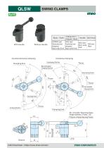
SWING CLAMPS R/ihUC Without Handle Body / Shaft CAD Download : https://www.imao.com/en/ imnocoRPORATion
Open the catalog to page 16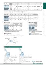
* ) Actual clamping height: 31.4 to 32.6 (clamping stroke: 1.2) **) Actual clamping height: 44.1 to 45.9 (clamping stroke: 1.8) ■With Handle ■Without Handle Part Number ***) Allowable load to operate the handle Part Number Note : The handle must be ordered separately. ■ [QLSLl STANDARD HANDLES ■ [qlTl[ ADJUSTABLE-TORQUE HANDLES ■Tip Installation Handles Push Up Pull Down Side Push next page
Open the catalog to page 17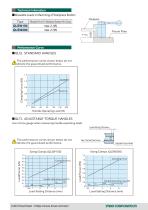
Technical Infomation ■Allowable Loads in Machining of Workpiece Bottom Type Allowable Force To Workpiece Bottom (Per Clamp) Performance Curve ■QLSL STANDARD HANDLES The performance curves shown below do not denote the guaranteed performance. Handle Operating Load (N) ■QLTL ADJUSTABLE-TORQUE HANDLES Use a force gauge when measuring handle-operating loads. Load-Setting Distance The performance curves shown below do not denote the guaranteed performance. Clamping Force Handle Operating Load (N) Clamping Force Adjustable-Torque Handle Handle Operating Load (N) Load-Setting Distance
Open the catalog to page 18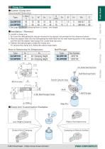
*) See page QLSW-SH clamping force vs. clamp - arm length ■Installation / Removal To install a clamp arm, 1. Fit it onto the shaft getting the stop pin received in the stop-pin slot provided on the clamp-arm bottom. 2. Place the adaptor head onto the shaft getting the shaft fitted into the shaft-receiving pocket in the adaptor head, and then lock the adaptor head using a hex. socket head cap screw. 3. Tighten the ball plungers inside the clamp arm. To remove the clamp arm, follow the above steps back. Ball Plunger Part Number Pocket for Clamp Arm Swing Shaft Ball Plunger ■Clamp Arm Customization...
Open the catalog to page 19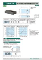
MACHINABLE CLAMP ARMS FOR SWING CLAMPS ReHS imno 2-M Ball Plungers LBSTH S45C steel Black oxide finish Part Number *) A clamping tip to mount on the end of the clamp arm must not weigh over 100g. ■ Clamp Arm Length Vs. Clamping Force Part Number ** ) Actual clamping height:33.4 to 34.6 (clamping stroke:1.2) ***) Actual clamping height:46.1 to 47.9 (clamping stroke:1.8)
Open the catalog to page 20
Value Creator Handles Push Up Pull Down Side Push
Open the catalog to page 21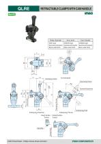
RETRACTABLE CLAMPS WITH CAM HANDLE R"»uc
Open the catalog to page 22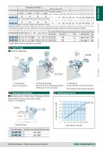
*) Clamping height can be adjusted. The parenthesised values denote actual clamping height. Part Number **) Allowable load to operate the handle Handles Push Up Pull Down Side Push Technical Information Performance Curve ■Allowable Loads in Machining of Workpiece Bottom Part Number
Open the catalog to page 23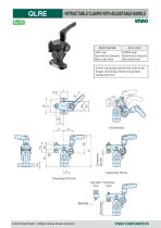
RETRACTABLE CLAMPS WITH ADJUSTABLE HANDLE Body/Spindle Screw clamping mechanism allows for longer clamping stroke and greater clamping force.
Open the catalog to page 24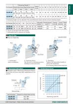
*) Clamping height can be adjusted. The parenthesised values denote actual clamping height. Part Number ** ) Studs are bonded with FKF handles. ***) Allowable load to operate the handle. Handles Push Up Pull Down Side Push Technical Information Performance Curve Part Number CAD Download : https://www.imao.com/en/ imnocoppoRnnon
Open the catalog to page 25All Imao Corporation catalogs and technical brochures
 Pneumatic Flex Locators
24 Pages
 One Touch Fasteners
160 Pages
 Vertical Clamps
20 Pages
 WORK SUPPORTS
31 Pages
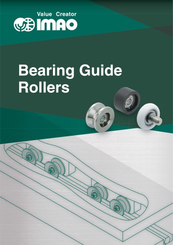 Bearing Guide Rollers
35 Pages
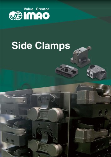 Side Clamps
27 Pages
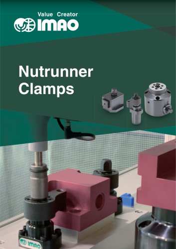 NUTRUNNER CLAMPS
24 Pages
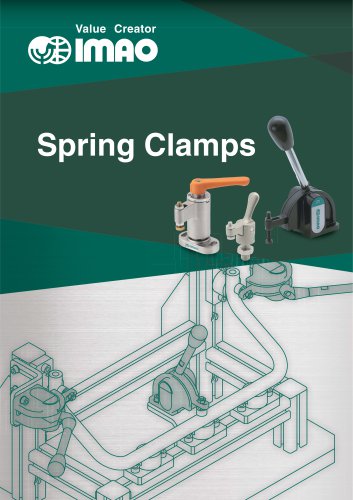 Spring Clamps
23 Pages
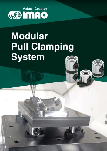 Modular Pull Clamping System
41 Pages
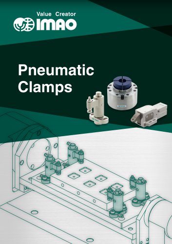 PNEUMATIC CLAMPS
46 Pages
 Machinable Collet Clamps
48 Pages
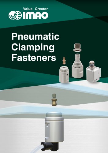 PNEUMATIC CLAMPING FASTENERS
16 Pages
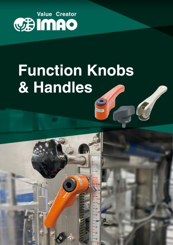 Function Knobs & Handles
22 Pages
 5-Axis Clamping Systems
15 Pages
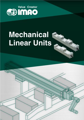 MECHANICAL LINEAR ACTUATORS
36 Pages
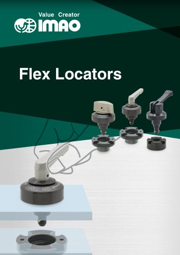 Flex Locators
46 Pages
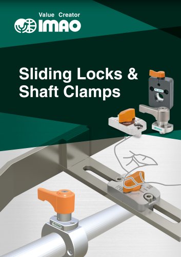 Sliding Locks & Shaft Clamps
58 Pages
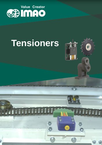 TENSIONERS
45 Pages
 HANDWHEELS & HANDLES
31 Pages
 SCREWS & NUTS
13 Pages
 CLAMPING KNOBS
22 Pages
 LOCATING PARTS
15 Pages
 GRIPPERS
28 Pages