- Catalogs
- Imao Corporation
- MECHANICAL LINEAR ACTUATORS
MECHANICAL LINEAR ACTUATORS
1 /36Pages
MECHANICAL LINEAR ACTUATORS
1 /36Pages
Catalog excerpts
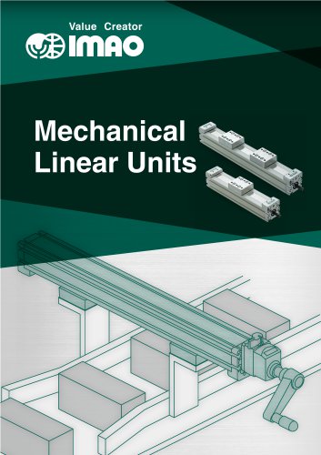
Value Creator Mechanical Linear Units
Open the catalog to page 1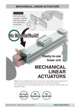
MECHANICAL LINEAR ACTUATORS Conventional Self-made linear actuators required selecting, making and assembling many parts. Ready-to-use linear unit MECHANICAL LINEAR ACTUATORS IMAO's pre-assembled Linear Unit can be used with simple manual adjustments without complex processes of parts selection, design and assembly. The internal parts are protected from dust by its aluminum profile body and dustproof sheet. No No No Parts Selection Designing Assembly
Open the catalog to page 2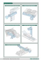
Application Example Stamping Rest Position Adjustment Stopper Position Adjustment Counting Sensor Position Adjustment Holder Belt Height Adjustment Conveyer Guide Adjustment
Open the catalog to page 3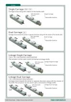
Carriage moves along with rotation of the handle shaft. Single Carriage *-Adjustable Gearbox Dual Carriage Carriages move towards the center or opposite directions along with the rotation of the handle shaft. With Adjustable Dual Carriage LAdjustable Gearbox [ CCW ] [ CW ] [ With Handle ShafH [ Without Handle Shaft ] The actuators can be used in pairs connected at linkage shafts. With Adjustable Linkage Single Carriage Gearbox _ _ __ _ _ __ LAdjustable Gearbox [ CW ] [ With Handle Shaf^ [ Without Handle Shaft ] Carriages move towards the center or opposite directions along with the rotation the...
Open the catalog to page 4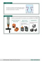
The abrasion resistance and self-lubricating material of sliding parts give the unit a longer lifetime against the load of up and down or sideways. Related Product Various accessories for actuators are available from IMAO. DIGITAL POSITION INDICATORS ONE-TOUCH SPINDLE LOCKS Secure locking of spindles with a quarter turn! HANDWHEELS Dedicated handwheels for actuators
Open the catalog to page 5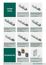
Linear Units MECHANICAL LINEAR ACTUATORS MECHANICAL LINEAR ACTUATORS WITH ADJUSTABLE GEARBOX MECHANICAL LINEAR ACTUATORS (Dual Carriage) MECHANICAL LINEAR ACTUATORS WITH ADJUSTABLE GEARBOX (Dual Carriage) MECHANICAL LINEAR ACTUATORS (Synchro-Use) MECHANICAL LINEAR ACTUATORS WITH ADJUSTABLE GEARBOX (Synchro-Use) MECHANICAL LINEAR ACTUATORS (Dual Carriage, Synchro-Use) MECHANICAL LINEAR ACTUATORS WITH ADJUSTABLE GEARBOX (Dual Carriage, Synchro-Use) ONE-TOUCH SPINDLE LOCKS POSITIONING PLATE
Open the catalog to page 6
DIGITAL POSITION INDICATORS DIGITAL POSITION INDICATORS ADAPTER SHAFTS PLASTIC KNURLED KNOBS PLASTIC SOLID DISK HANDWHEELS PLASTIC ANGLED-SPOKE HANDWHEELS
Open the catalog to page 7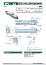
MECHANICAL LINEAR ACTUATORS Body Technical Information of Mechanical Linear Actuators Choose the optional elements for your needs. ■One-Touch Spindle Locks ■Positioning Plate ■Digital Position Indicators ■Adapter Shafts
Open the catalog to page 8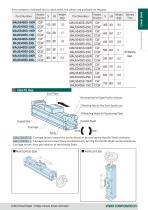
Part numbers in boldtext are in-stock items, the others are available on request. Part Number Part Number Linear Units How To Use CAD Download : https://www.imao.com/en/ imflo corporator
Open the catalog to page 9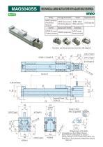
MECHANICAL LINEAR ACTUATORS WITH ADJUSTABLE GEARBOX Body Gearbox can be positioned at every 90 degree.
Open the catalog to page 10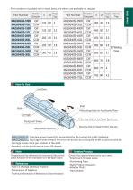
Part numbers in boldtext are in-stock items, the others are available on request. Part Number Part Number Linear Units How To Use ■ IMAG5040SS-R I : Carriage moves toward the arrow direction by turning the shaft clockwise. ■ IMAG5040SS-L |: Carriage moves toward the arrow direction by turning the shaft counterclockwise. ■Carriage moves 3mm per rotation of the shaft. ■Gearbox can be positioned at every 90 degree. Related Product The gearbox will be delivered with mounted to Mechanical Linear Actuators in the orientation as in the figure above. Reference ■How To Change Gearbox Position ■Dimensions...
Open the catalog to page 11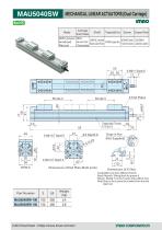
MECHANICAL LINEAR ACTUATORS (Dual Carriage) Body Trapezoidal Thread Part Number
Open the catalog to page 12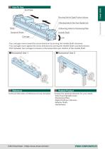
Mounting Hole for Digital Position Indicator 2 Mounting Holes for One-Touch Spindle Lock Body 4 Mounting Holes for Positioning Plate Dustproof Sheet Handle Shaft ・Two carriages move toward the arrow directions by turning the Handle Shaft clockwise. ・Two carriages move against the arrow directions by turning the Handle Shaft counterclockwise. ・Pitch between two carriages increases or decreases 6mm per rotation of the Handle Shaft. Reference Technical Information of Mechanical Linear Actuators Related Product Choose the optional elements for your needs. ・One-Touch Spindle Locks ・Positioning Plate...
Open the catalog to page 13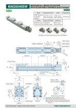
MECHANICAL LINEAR ACTUATORSWITH ADJUSTABLE GEARBOX (Dual Carriage) Body Gearbox can be positioned at every 90 degree.
Open the catalog to page 14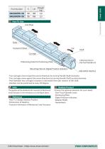
Linear Units Part Number Body Dustproof Sheet Carriage 2 Mounting Holes for One-Touch Spindle Lock 4 Mounting Holes for Positioning Plate Mounting Hole for Digital Position Indicator Adjustable Gearbox ・Two carriages move toward the arrow directions by turning Handle Shaft clockwise. ・Two carriages move against the arrow directions by turning Handle Shaft counterclockwise. ・Pitch between two carriages increases or decreases 6mm per rotation of the shaft. ・Gearbox can be positioned at every 90 degree. Note The gearbox will be delivered with mounted to Mechanical Linear Actuators in the orientation...
Open the catalog to page 15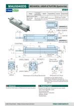
MECHANICAL LINEAR ACTUATORS (Synchro-Use) On Request Carriage End Plates Dustproof Sheet A6N01 aluminum ZDC2 S45C steel SCM435 steel SUS304H die-cast zinc Anodized CAC902 copper alloy Black oxide finish Trivalent chromate stainless steel Natural Chrome plated (Without Handle Shaft) Handle Shaft (With Handle Shaft) Dimensions of End Plate (Both ends) Compatible nuts from different brands: Bosch Rexroth: Sliding block for groove 6 Misumi: Sliding T-nut for 5 series (slot width 6 mm) Note:Drop-in nuts cannot be inserted from the end plate slot. Reference Technical Information of Mechanical Linear...
Open the catalog to page 16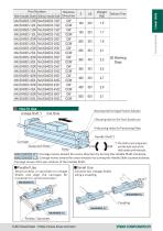
Delivery Time Linear Units Rotative With Handle Shaft Without Handle Shaft Direction Part Number Mounting Hole for Digital Position Indicator 2 Mounting Holes for One-Touch Spindle Lock 4 Mounting Holes for Positioning Plate Handle Shaft *) Carriage *) The shaft is one component and the both ends of the Body shaft rotate synchronously. ・ MAU5040DS-R,Y :Carriage moves toward the arrow direction by turning the Handle Shaft clockwise. ・ MAU5040DS-L,Z :Carriage moves toward the arrow direction by turning the Handle Shaft counterclockwise. ・Carriage moves 3mm per rotation of the Handle Shaft. Dustproof...
Open the catalog to page 17All Imao Corporation catalogs and technical brochures
 Pneumatic Flex Locators
24 Pages
 One Touch Fasteners
160 Pages
 Vertical Clamps
20 Pages
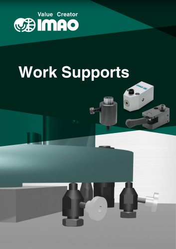 WORK SUPPORTS
31 Pages
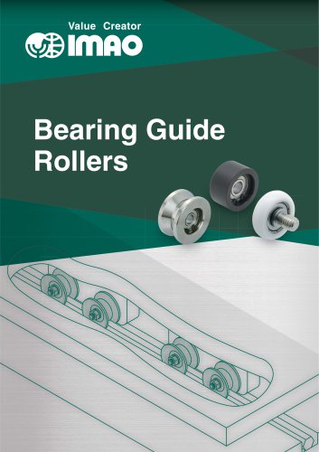 Bearing Guide Rollers
35 Pages
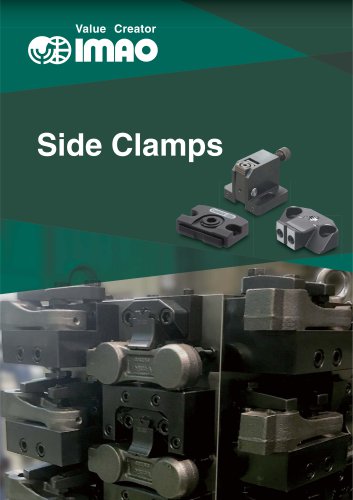 Side Clamps
27 Pages
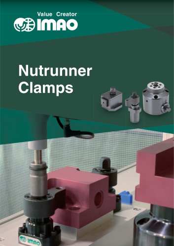 NUTRUNNER CLAMPS
24 Pages
 Spring Clamps
23 Pages
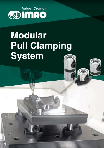 Modular Pull Clamping System
41 Pages
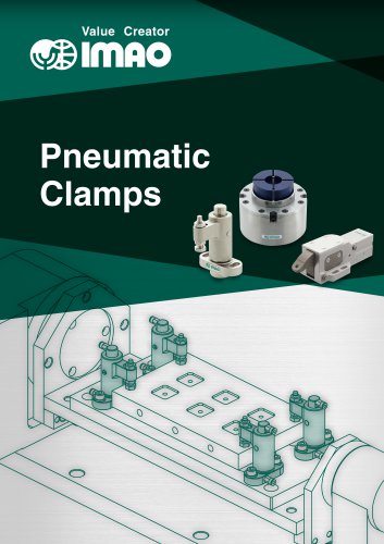 PNEUMATIC CLAMPS
46 Pages
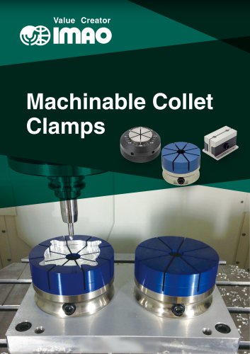 Machinable Collet Clamps
48 Pages
 PNEUMATIC CLAMPING FASTENERS
16 Pages
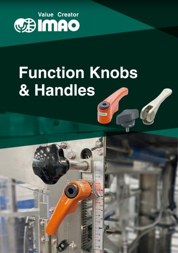 Function Knobs & Handles
22 Pages
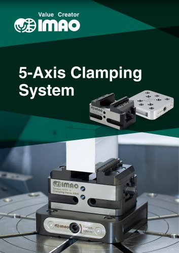 5-Axis Clamping Systems
15 Pages
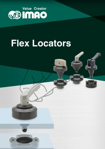 Flex Locators
46 Pages
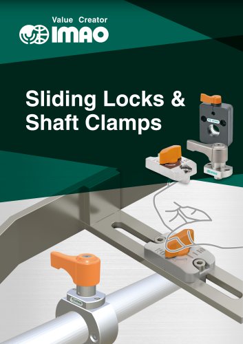 Sliding Locks & Shaft Clamps
58 Pages
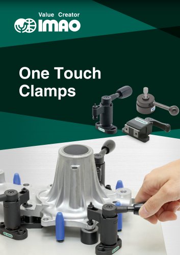 ONE TOUCH CLAMPS
68 Pages
 TENSIONERS
45 Pages
 HANDWHEELS & HANDLES
31 Pages
 SCREWS & NUTS
13 Pages
 CLAMPING KNOBS
22 Pages
 LOCATING PARTS
15 Pages
 GRIPPERS
28 Pages