- Catalogs
- Imao Corporation
- Function Knobs & Handles
Function Knobs & Handles
1 /22Pages

Function Knobs & Handles
1 /22Pages
Catalog excerpts

Value Creator Function Knobs & Handles
Open the catalog to page 1
Knobs TORQUE LIMITING KNOBS ONE-TOUCH LOCKING KNOBS Clamping Handles POINTER PLATE ADJUSTABLE-TORQUE HANDLES COMPACT CAM HANDLES QLCCS
Open the catalog to page 2
Value Creator
Open the catalog to page 3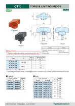
TORQUE LIMITING KNOBS imno (Tapped) ★ Key Point-v [ Tightening end is detectable by sound and touch of a click. ^ ■Tapped ■ Stud Part Number Part Number **) Use these values only as a guide. <Tightening force (kN) = Torque(N-m)/{0.2Xd(mm)} d:Nominal diameter of the stud>
Open the catalog to page 4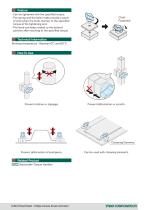
Feature ・Can be tightened with the specified torque. ・The spring and the balls inside provide a touch of click when the knob reaches to the specified torque at the tightening end. ・The knob can keep rotated to the desired position after reaching to the specified torque. Click! Fastened! Technical Information Working temperature : Between 0℃ and 80 ℃ Prevent rotation or slippage. Prevent deformation or scratch. Clamping Elements Prevent deformation of workpiece. Related Product ATCL Adjustable-Torque Handles Can be used with clamping el
Open the catalog to page 5
Value Creator
Open the catalog to page 6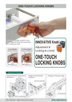
ONE-TOUCH LOCKING KNOBS Can lock the spindle rotation in one action. Ideal for fixing rack and pinion axis or leadscrew axis. (Position adjustable) (Position adjusted) to Blue= Safety operate machine to Red=Caution opearate machine INNOVATIVE Knob! Adjustment & Locking at a time! ONE-TOUCH LOCKING KNOBS Application Example Adjsutment of film tension in printing machine (Rack and pinion) Changes of camera position (Leadscrew) Changes of shooter angle ONE-TOUCH LOCKING KNOB ONE-TOUCH LOCKING KNOB ONE-TOUCH LOCKING KNOB
Open the catalog to page 7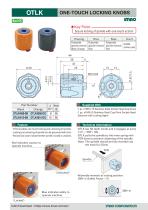
OTLK ONE-TOUCH LOCKING KNOBS [ Secure locking of spindle with one-touch action! i ■ OTLK enables one-touch locking and unlocking of spindle. ■ Locking and unlocking of spindle can be perceived with click. ■ Red and blue colors indicate whether spindle is locked or unlocked. Red indicates caution to operate machine. ■OTLK has 50 teeth inside and it engages at every 7.2°( = 360°/ 50). ■OTLK pulls the spindle by the inner spring with 70N force to prevent chattering of the spindle. Note: The spindle should be fully inserted into the knob for 25mm.
Open the catalog to page 8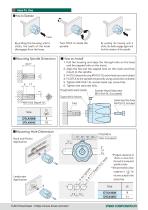
■ Mounting Spindle Dimension ■ How to Install 1. Pull the housing and align the through hole on the base and the tapped hole on the insert. 2. Align the flat and the tapped hole on the insert and then mount to the spindle. 3. Fix OTLK temporarily using M5X0.8-15L socket-head cap screw included. 4. Fix OTLK to the spindle temporarily using a setscrew included. 5. Tighten M5X0.8-15L socket-head cap screw fully. 6. Tighten the setscrew fully. Mounting Hole Dimension )Prepare clearance of 13mm or more from the end of a required spindle stroke. ) Recommended surface roughness is 1^6 ’ for the inner...
Open the catalog to page 9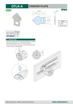
POINTER PLATE imno Body Part Number ■ Use with scale plate for reading graduations in radial feeding applications such as rack and pinion. ■ Insert Pointer Plate to the slot on the base component of One-Touch Locking Knobs. CAD Download : https://www.imao.com/en/ imnocoRPORRTion
Open the catalog to page 10
Value Creator
Open the catalog to page 11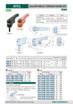
ATCL ADJUSTABLE-TORQUE HANDLES (Tapped) Type/Size *) Use this tightening force information as an indication. (Tightening Force(kN) = Torque(N-m) /{0.2Xd(mm)} d: nominal screw diameter) Part Number ■The handle is adjustable. ■ Handle that allows setting a desired tightening torque. ■When the desired torque is reached, the handle clicks to indicate completed tightening. Tapped type ■Tapped type has a through hole \ that can be used with bolts.
Open the catalog to page 12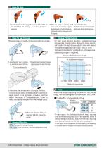
I.Lift the handle to disengage 2.Turn the handle to the teeth from the locking a desired position. element. 3.When the handle is released, the 4.Turn the handle to clamp. return spring automatically engages The handle clicks to indicate completed the teeth again for further tightening. tightening at desired tightening torque. The handle can be positioned every 30 degrees. ■For initial several thousand operations, the tightening torque decreases.(See the graph below.) Measure the torque regularly, and fine adjust the depth of torque-adjusting screw when needed. ■The tightening torque can vary....
Open the catalog to page 13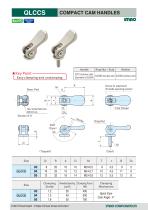
QLCCS COMPACT CAM HANDLES CAD Download : https://www.imao.com/en/ imnocoRPORRTion
Open the catalog to page 14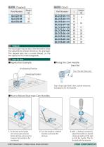
Part Number Part Number Feature The stud type ring nut has a fine thread to allow fine adjustment of lever direction, tilt, and load. The tapped type has a coarse thread, so the two types are not interchangeable. ■Application Example ■Fixing the Cam Handle Brass Pad Unclamping Position Hex. Socket Setscrew Clamping Position Use a brass pad and a hex. socket setscrew included to fix the handle. ■How to Mount Stud-type Cam Handles 1Fix the stud to the handle with a brass pad and a hex socket setscrew and screw the Compact Cam Handle to the counterpart. 2Turn the handle to a desired direction and...
Open the catalog to page 15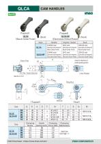
(Tapped) QLCA (Black Oxide Finish) CAM HANDLES (Tapped) QLCA-NP
Open the catalog to page 16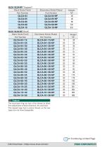
QLCAl IQLCA-NPI (Stud) Black Oxide Finish The stud type ring nut has a fine thread to allow fine adjustment of lever direction, tilt, and load. The tapped type has a coarse thread, so the two types are not interchangeable. Continuing on Next Page
Open the catalog to page 17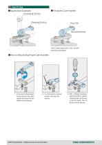
■Application Example Unclamping Position Clamping Position Hex.Socket Setscrew Use a brass pad and a hex. socket setscrew included. ■How to Mount Stud-type Cam Handles 1. Fix the stud to the handle with a brass pad and a hex socket setscrew and screw the Cam Handle to the counterpart. 2. Turn the handle to a desired direction and loosen the setscrew. 3. With a flathead screwdriver, adjust the handle to a desired clamping height and the load to fold the handle. Then fix the stud with the setscr
Open the catalog to page 18
Value Creator
Open the catalog to page 19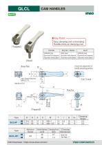
Easy clamping and unclamping. Handle clicks at clamping end.
Open the catalog to page 20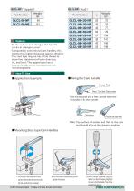
QLCL-NP (Stud) Feature By its unique cam design, the handle clicks at clamping end. Compared to conventional cam handles, this product has higher resistance against vibration. The stud type ring nut has a fine thread to allow fine adjustment of lever direction, tilt, and load. The tapped type has a coarse thread, so the two types are not interchangeable. Fixing the Cam Handle Use a brass pad and a hex. socket setscrew included to fix the handle. Note: Top surface of washer and flats at the cam end should align at the clamping position. pad and a hex socket setscrew and screw the Cam Handle to...
Open the catalog to page 21All Imao Corporation catalogs and technical brochures
 Pneumatic Flex Locators
24 Pages
 One Touch Fasteners
160 Pages
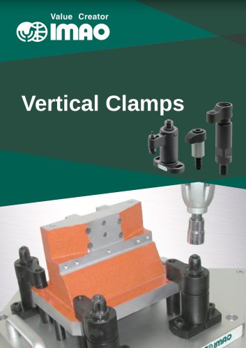 Vertical Clamps
20 Pages
 WORK SUPPORTS
31 Pages
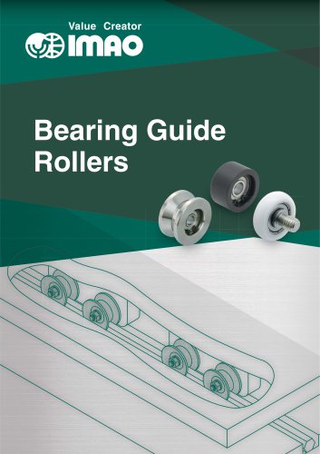 Bearing Guide Rollers
35 Pages
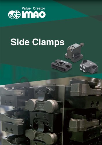 Side Clamps
27 Pages
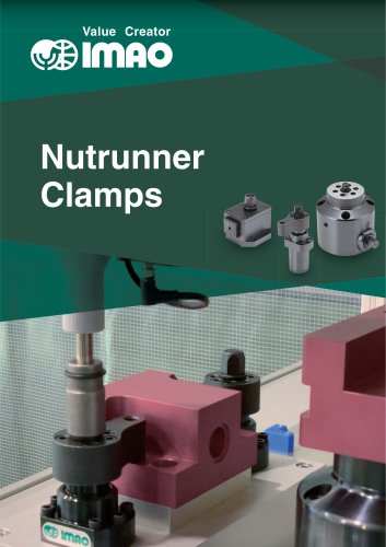 NUTRUNNER CLAMPS
24 Pages
 Spring Clamps
23 Pages
 Modular Pull Clamping System
41 Pages
 PNEUMATIC CLAMPS
46 Pages
 Machinable Collet Clamps
48 Pages
 PNEUMATIC CLAMPING FASTENERS
16 Pages
 5-Axis Clamping Systems
15 Pages
 MECHANICAL LINEAR ACTUATORS
36 Pages
 Flex Locators
46 Pages
 Sliding Locks & Shaft Clamps
58 Pages
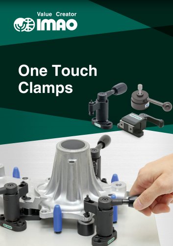 ONE TOUCH CLAMPS
68 Pages
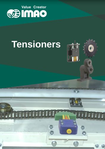 TENSIONERS
45 Pages
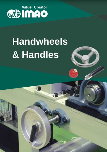 HANDWHEELS & HANDLES
31 Pages
 SCREWS & NUTS
13 Pages
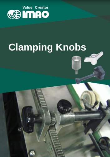 CLAMPING KNOBS
22 Pages
 LOCATING PARTS
15 Pages
 GRIPPERS
28 Pages