- Catalogs
- The Imaging Source Europe GmbH
- 2-Inch System-On-A-Chip (SOC) CMOS Digital Image Sensor
2-Inch System-On-A-Chip (SOC) CMOS Digital Image Sensor
1 /18Pages

2-Inch System-On-A-Chip (SOC) CMOS Digital Image Sensor
1 /18Pages
Catalog excerpts

Preliminary* MT9D131: 1/3.2-Inch 2-Mp SOC Digital Image Sensor Features Table 1: Key Performance Parameters PDF: 09005aef824c90ce/Source: 09005aef824c90d6 Micron Technology, Inc., reserves the right to change products or specifications without notice. MT9D131_LDS_1 .fm - Rev. B 3/07 EN 1 ©2006 Micron Technology, Inc. All rights reserved. tProducts and specifications discussed herein are for evaluation and reference purposes only and are subject to change by Micron without notice. Products are only warranted by Micron to meet Micron's production data she
Open the catalog to page 1
MT9D131: 1/3.2-Inch 2-Mp SOC Digital Image Sensor General Description General Description Micron Imaging MT9D131 is a 1/3.2 inch, 2-megapixel CMOS image sensor with an integrated advanced camera system. The camera system features a microcontroller (MCU) and a sophisticated image flow processor (IFP) with a real-time JPEG encoder. The sensor core consists of an active pixel array of 1668 x 1248 pixels, programmable timing and control circuitry including a PLL, analog signal chain with automatic offset correction and programmable gain, and two 10-bit A/D converters (ADC). The entire system-on-a-chip...
Open the catalog to page 2
MT9D131: 1/3.2-Inch 2-Mp SOC Digital Image Sensor Typical Connection Typical Connection Typical Configuration (Connection) SADDR SCLK SDATA DOUT0-DOUT7 LINE_VALID FRAME_VALID PIXCLK To CMOS Camera Port EXTCLK RESET# Notes: 1. Resistor value 1.5KΩ is recommended, but may be greater for slower two-wire speed. 2. TEST must be connected to digital ground for normal device operation. 3. All power supply pads must be used. Micron Technology, Inc., reserves the right to change products or specifications without notice. ©2006 Micron Technology, Inc. All rights rese
Open the catalog to page 3
d^crorv Signal Description MT9D131: 1/3.2-Inch 2-Mp SOC Digital Image Sensor Signal Description Table 3: Signal Description Micron Technology, Inc., reserves the right to change products or specifications without notice. ©2006 Micron Technology, Inc. All rights reserved.
Open the catalog to page 4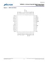
d^crorvFigure 3: 48-Pin CLCC Pinout MT9D131: 1/3.2-Inch 2-Mp SOC Digital Image Sensor Signal Description ^^CC^CC — — -Z.-Z.-Z. Micron Technology, Inc., reserves the right to change products or specifications without notice. ©2006 Micron Technology, Inc. All rights reserved.
Open the catalog to page 5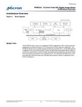
MT9D131: 1/3.2-Inch 2-Mp SOC Digital Image Sensor Architecture Overview Architecture Overview Figure 4: Block Diagram Image Flow Processor Decimator Line Buffers Interpolation Line Buffers Sensor Core JPEG Line Buffers Color Pipeline Stats Engine Other JPEG Memories Micron controller Sensor Core The MT9D131 sensor core is a 2-megapixel CMOS image sensor with a 2.8µm pixel size designed for an optical format of 1/3.2 inches with a UXGA maximum resolution. The MT9D131 sensor core includes a phase-locked loop oscillator (PLL), to facilitate camera integration and minimize the system cost for wireless...
Open the catalog to page 6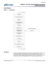
MT9D131: 1/3.2-Inch 2-Mp SOC Digital Image Sensor Architecture Overview Color Pipeline Figure 5: Color Pipeline DATA, SYNC IN Test Pattern Black Level Subtraction Digital Gain Lens Shading Correction with Digital Gain Line Buffers Defect Correction MEASUREMENT ENGINE Interpolation and Edge Detection Gamma Correction YUV-to-RGB/YUV Conversion Format Output DATA, SYNC OUT Test Pattern During normal operation of MT9D131, a stream of raw image data from the sensor core is continuously fed into the color pipeline. For test purposes, this stream can be replaced with a fixed image generated by a special...
Open the catalog to page 7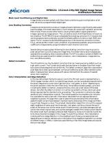
MT9D131: 1/3.2-Inch 2-Mp SOC Digital Image Sensor Architecture Overview Black Level Conditioning and Digital Gain Image stream processing starts with black level conditioning and multiplication of all pixel values by a programmable digital gain. Lens Shading Correction Inexpensive lenses tend to produce images whose brightness is significantly attenuated near the edges. Chromatic aberration in such lenses can cause color variation across the field of view. There are also other factors causing fixed-pattern signal gradients in images captured by image sensors. The cumulative result of all these...
Open the catalog to page 8
MT9D131: 1/3.2-Inch 2-Mp SOC Digital Image Sensor Architecture Overview Color Correction and Aperture Correction To achieve good color fidelity of IFP output, interpolated RGB values of all pixels are subjected to color correction. The IFP multiplies each vector of three pixel colors by a 3 x 3 color correction matrix. The three components of the resulting color vector are all sums of three 10-bit numbers. Since such sums can have up to 12 significant bits, the bit width of the image data stream is widened to 12 bits per color (36 bits per pixel). The color correction matrix can be either programmed...
Open the catalog to page 9
MT9D131: 1/3.2-Inch 2-Mp SOC Digital Image Sensor Architecture Overview pixel array, and/or by binning 2 x 2 groups of pixels of the same color. Since decimation by skipping (that is, deletion) can cause aliasing (even if pixel binning is simultaneously enabled), it is generally better to change image size only by cropping and pixel binning. The image cropping and decimator module can be used to do digital zoom and pan. If the decimator is programmed to output images smaller than images coming from the sensor core, zoom effect can be produced by cropping the latter from their maximum size down...
Open the catalog to page 10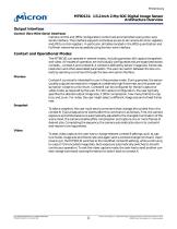
MT9D131: 1/3.2-Inch 2-Mp SOC Digital Image Sensor Architecture Overview Output Interface Control (Two-Wire Serial Interface) Camera control and JPEG configuration/control are accomplished using a two-wire serial interface. The interface supports individual access to all camera function registers and JPEG control registers. In particular, all tables located in the JPEG quantization and Huffman memories are accessible using the two-wire interface. Context and Operational Modes The MT9D131 can operate in several modes, including preview, still capture (snapshot), and video. All modes of operation...
Open the catalog to page 11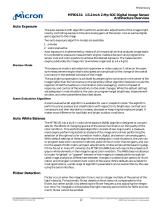
MT9D131: 1/3.2-Inch 2-Mp SOC Digital Image Sensor Architecture Overview Auto Exposure The auto exposure (AE) algorithm performs automatic adjustments of the image brightness by controlling exposure time and analog gains of the sensor core as well as digital gains applied to the image. Two auto exposure algorithm modes are available: 1. preview 2. scene evaluative Auto exposure is implemented by means of a firmware driver that analyzes image statistics collected by exposure measurement engine, makes a decision and programs the sensor core and color pipeline to achieve the desired exposure. The...
Open the catalog to page 12All The Imaging Source Europe GmbH catalogs and technical brochures
 MT9T031
12 Pages
 MT9P031
45 Pages
 MT9J003
77 Pages
 IMAGINGSOURCE- Catalog
172 Pages
 dfgsdg
2 Pages

- DC power supply
- AC/DC power supply
- Electrical cable
- Digital imager
- Visible imager
- Industrial camera module
- Infrared imager
- Monitoring camera system
- Full-color camera system
- Single-output power supply
- USB camera module
- Electrical data cable
- Image processing camera module
- Monochrome camera module
- GigE Vision camera
- Compact imager
- Industrial cable
- Switch electrical cable