- Catalogs
- Imagine Optic
- Optical metrology measurements with HASOTM - SWIR optical metrology Application Notes

Optical metrology measurements with HASOTM - SWIR optical metrology Application Notes
Optical metrology measurements with HASOTM - SWIR optical metrology Application Notes
This document details the application of HASOTM wavefront sensors for characterizing the optical quality of a complex lens system. The imager, designed to minimize distortion and aberrations, consists of five lenses. The HASO3 128 GE2 sensor was chosen for its high spatial resolution, though other HASOTM sensors could be used similarly.
Experimental Setup
The complex lens operates at a magnification of 0.2x with a numerical aperture (NA) of 0.3. The HASOTM sensor, suitable for NA up to 0.1, is used on the image side. A fibered laser diode source is placed in the image plane due to mechanical constraints. The setup includes eight micro-adjusters for precise alignment of the light source, microscope objective, and HASOTM sensor.
Light Source Alignment
Without the microscope objective, the light source is aligned by measuring magnification along the zsource direction. The HASOTM sensor determines the focal point position, aiding in precise optical element positioning. Magnification is calculated by comparing source movements and corresponding sensor readings.
Field Curvature and Distortion Measurements
Field curvature is assessed by plotting the "Radius" parameter for various source positions. Distortion, indicated by magnification changes across the field, is measured by comparing local and global magnifications. Distortion is found to be less than 1%.
Microscope Objective Alignment
After achieving correct magnification, the light source and HASOTM are aligned through the complex lens. The microscope objective is added and aligned to minimize tilt, ensuring the setup is correctly centered. Aberrations from the microscope objective are calibrated and subtracted from measurements.
Optical Characterization
The setup is used to map wavefront error (WFE) across the complex lens field. The optical axis is determined by the minimum WFE value. Wavefront decomposition using Zernike polynomials reveals centering issues, with Coma 90° indicating misalignment of optical elements. After subtracting 3rd order aberrations, 5th order spherical aberration is identified as the main aberration.
Conclusion
The HASO3 128 GE2 sensor effectively measures distortion, curvature, and wavefront aberrations, identifying optical axis and eccentricity defects in the complex lens. These findings validate the lens fabrication against its optical model.
Catalog excerpts

Optical metrology measurements with HASOTM Imagine Optic, 18 rue Charles de Gaulle, 91400 Orsay, France [email protected] Imagine Optic offers a wide range of products (hardware and software), which can be used together to accurately characterize the optical quality of a complex optical systems. For instance the wavefront sensors from HASOTM line are perfectly suited for metrological characterization. They can accurately measure distortion, field curvature, wavefront error and optical aberrations. Based on a patented Shack-Hartmann technology, HASOTM wavefront sensors by Imagine Optic contain an association of a microlens grid and a detector in order to calculate local derivatives of the wavefront and this way it can reach the accuracy of /100 RMS (Root Mean Square). This document presents an example of HASOTM wavefront sensor application to characterize the optical quality of a complex lens. Optical metrology measurements with HASO N.Varkentina www.imagine-optic.com 20 October 2020 – Property of Imagine Optic
Open the catalog to page 1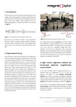
1. Introduction This document presents the optical characterization of an imager, which was designed to introduce as little distortion as possible, with a limited amount of aberrations across its field of view. This imager, called complex lens in the following paragraphs, is made of five lenses, as it is shown in Figure 1. Figure 1. The optical layout of the imager (complex lens). We chose to use HASO3 128 GE2 in this experiment, Figure 3. Experimental setup with definition of axes. because it offers a very high spatial resolution. However, Our experimental setup (see Figure 3) has total of eight...
Open the catalog to page 2
Figure 6. shows magnification measurements for different positions along zsource direction, allowing the accurate estimation of the conjugation plane location. 0.203 source position along zsource (mm) Figure 6. Magnification along zsource. Figure 4. Example of alignement parameters provided by WaveView. However, for collimated beams, the “Chief ray” panel gives Once the correct conjugation location along zsource is determined, it should remain unchanged for the rest of the measurements. useful information concerning the beam’s tilt and curvature. Those parameters, in turn, assist in precise For...
Open the catalog to page 3
local changes in magnification do not show any particular tendency, so we can conclude that distorsion is less than 1%. 5. Alignment of the microscope objective Once the correct magnification adjustement is achieved, the further optical characterization requires to accurately align the source and the HASOTM through the complex lens. After roughly positioning the light source in the complex lens center, the micro-adjusters 4 and 5 should be used in order to minimize the “(X,Y) positions” parameters inside WaveView software (see Figure 4). This procedure ensures that the image plane is centered...
Open the catalog to page 4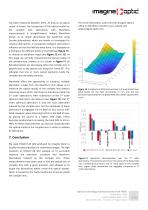
has been measured between them. As long as its optical center is known, the comparison of the optical model for the For more information, and to find the Imagine Optic’s office or distributor nearest to you, please visit www.imagine-optic.com measurements is straightforward. Indeed, WaveView allows us to simply decompose the wavefront using Zernike polynomials, which are known to correspond to classical aberrations. A comparison between aberration’s influence across the field has been done. It is displayed as a histogram for different points in the field (see Figure 11), or directly as wavefront...
Open the catalog to page 5
Figure 12. Wavefront evolution accros the work field. Coma is significant on axis, which is characteristic of an excentricity defect. Astigmatism appears with the field and prevails at the edge of the field. Figure 13. Wavefront evolution accros the work field, without the 3rd order aberrations influence. The 5th order spherical aberration is predominant on axis, but the trefoil prevails at the edge of the work field. Optical metrology measurements with HASO Application note www.imagine-optic.com 20 October 2020 – Property of Imagine Optic
Open the catalog to page 6All Imagine Optic catalogs and technical brochures
 WAVE Suite
3 Pages











Archived catalogs
 HASO™3 Wavefront Sensors
3 Pages
 SL-Sys neo
2 Pages
 SL-Sys LIQUID
2 Pages
 HASO R-Flex
3 Pages
 HASO?3 WSR Wavefront Sensors
2 Pages
 bendAO?
3 Pages
 HASO3
HASO32 Pages
 HASO R.FLEX
4 Pages
 absolute measurement
4 Pages
 Telescope characterization
3 Pages
 NIR optics characterization
6 Pages
 Large deformable mirror ILAO
6 Pages
 AO in femtosecond laser
5 Pages
 AO inside laser chain
5 Pages
 Microtraps
4 Pages