


- Products
- Catalogs
- News & Trends
- Exhibitions
JEI® CATALOGUE

JEI® CATALOGUE
INDUSTRIA LOMBARDA MATERIALE ELETTRICO SpA (ILME) has been a significant player in the electrotechnical sector since 1938, focusing on industrial installations. Known for innovation, customer service, and environmentally-friendly practices, ILME operates globally, especially in automation-leading countries like Germany and Japan.
Since January 1997, electrical products in Europe must bear the CE marking, indicating compliance with EU directives. ILME products comply with the Low Voltage Directive and other relevant standards, ensuring safety and quality. The CE marking acts as a self-certification of safety, although ILME products also carry voluntary conformity markings.
ILME offers a range of connectors under the JEI® series, suitable for industrial environments. These connectors are made from UL 94 V-0 thermoplastic resin and feature various termination methods, including screw, crimp, and spring connections. The JEI® series is designed for reliability and flexibility, with options for different pole densities and connection types.
ILME emphasizes the importance of proper installation to ensure safety and functionality. Connectors should not be connected or disconnected under load, and proper tools and techniques should be used for wiring. The company provides guidelines to maintain the IP protection rating and ensure compatibility with other products.
The JEI® inserts are designed for high performance, with options for different voltage and current ratings. The SQUICH® quick connection system offers tool-free wiring, reducing cabling time significantly. The connectors are compatible with similar products from other manufacturers, although full compatibility cannot be guaranteed due to potential changes by other manufacturers.
ILME provides comprehensive solutions for heavy-duty electrical connections, ensuring compliance with safety standards and offering a range of products to meet diverse industrial needs.
Multipole connectors for industrial purposes are designed with thermoplastic levers and insulating enclosures. They include protective earth terminals with wide contact surfaces and can be connected using captive screws or spring terminals.
The document references the European standard EN 61984 (2009-06) for safety prescriptions of multipole connectors, which aligns with the international standard IEC 61984. This standard applies to connectors with rated voltages over 50V and up to 1000V, and rated currents up to 125A per pole. It introduces the concept of connectors without breaking capacity (COC) and refers to other standards for terminal security and performance requirements.
Overvoltage categories (I to IV) are defined based on transient overvoltage values. Table 1 provides rated impulse withstand voltages for equipment powered from low-voltage mains, with examples of equipment belonging to different categories.
Pollution degrees (1 to 4) are defined based on the presence of foreign matter affecting dielectric strength. Pollution degree 3 is typical for industrial environments, while degree 2 is for household environments. EN 61984 allows for sizing insulation distances for connectors in enclosures with protection class ≥IP54 for a lower pollution degree.
Insulating materials are classified into groups based on their resistance to tracking, measured by the Comparative Tracking Index (CTI). The ILME connectors use materials from groups IIIa/IIIb.
The document discusses the determination of insulation clearance based on rated impulse withstand voltage, electric field conditions, altitude, and micro-environment. It provides guidelines for determining clearances and creepage distances according to IEC 60664-1.
The rated voltage is assigned by the manufacturer and may vary for different connectors. The document provides guidelines for choosing the rated impulse withstand voltage based on nominal supply voltage and overvoltage category.
The document outlines the rated impulse withstand voltages for various voltage levels, with specific values used in the United States, Canada, and Japan. It references IEC 60664-1 for determining minimum clearance through-air insulation distances.
Minimum clearance for insulation coordination is specified, with changes noted from previous editions of IEC 60664-1. The document details the requirements for impulse withstand voltage tests, including conditions under which these tests are necessary.
The document refers to IEC 60664-1 and EN 61984 standards for determining insulation distances and testing procedures. It specifies the conditions under which rated impulse withstand voltage declarations are optional or required.
For components respecting minimum through-air insulation distances, impulse voltage withstand tests may be exempted. The document advises on designing insulation surfaces to avoid continuous conductive pollution paths.
- Table F.1 provides rated impulse withstand voltages.
- Table F.2 outlines minimum clearances for insulation coordination.
- Test voltages for rated impulse withstand voltage are detailed, with adjustments for altitude.
- Tables F.3a and F.3b provide rationalized voltages for single-phase and three-phase systems, respectively.
- The document emphasizes the importance of adhering to specified insulation distances to ensure safety and compliance with standards.
- It highlights the impact of pollution degree on insulation requirements and the necessity of considering these factors in design and testing.
This document outlines the specifications and safety prescriptions for cable grippers with metric threads according to EN 60423. It highlights the transition from Pg size series to metric series for cable grippers, which became effective on 1st April 2001.
The document specifies the use of metric threads for cable grippers but does not detail dimensions such as wrench size or seal dimensions. The transition from Pg to metric threads was intended to end by 1st March 2001, although Pg devices can still be used as spare parts.
The document details the IP protection ratings according to EN 60529, which are applicable to enclosures for electric materials with a rated power no greater than 72.5 kW. The protection levels range from IP44 to IP69, each offering varying degrees of protection against solid objects and water.
Several series of enclosures are described, including:
- JCV and JMV series: Made of die-cast aluminum with epoxy-polyester coating, featuring oil-resistant gaskets and galvanized steel locking devices.
- JP series: Similar to JCV and JMV but with thermoplastic locking devices and IP65 protection.
- CK and MK series: Made of self-extinguishing thermoplastic material, offering IP65 protection and suitable for environments where powder paint is not recommended.
- COB series: Allows the use of multipole connectors within electric panels without traditional metallic enclosures, offering cost and space savings.
The document describes the use of coding pins to prevent incorrect coupling of connector inserts, ensuring that identical connectors with different functions are not mismatched.
This document provides a comprehensive overview of the transition to metric threads for cable grippers, the IP protection standards, and the various enclosure options available for industrial applications.
1. Female inserts (JKF 03, JKF 04) and male inserts (JKM 03, JKM 04) are designed for screw terminal connections. They comply with EN 61984 standards, supporting 10A at 230/400V with a 4kV impulse withstand voltage. The insulation resistance is ≥ 10 GΩ, and they operate within an ambient temperature range of -40°C to +100°C. The inserts are made from self-extinguishing thermoplastic resin UL 94 V1 and have a mechanical life of ≥ 200 cycles. Contact resistance is ≤ 1 mΩ.
2. The JKS series offers spring terminal connections, allowing for easy wire insertion without special preparation. They support wire sections from 0.14 to 2.5 mm² (AWG 26-14) and have a mechanical endurance of ≥ 500 cycles. The rated current is 10A at 400V, with a pollution degree of 3 and an ambient temperature limit of -40°C to +125°C. The degree of protection varies from IP20 to IP69K depending on the enclosure type.
- Conductors should be stripped to a length of 6 mm for screw terminals and 9-11 mm for spring terminals. A screwdriver with a 0.5x3 mm blade is recommended for both types of connections.
- The products are certified by UL and EAC, with additional cUL certification for the JKS series.
- For maximum current load, refer to the load curves provided in the diagrams. Coding pins are optional for specific configurations.
- The document includes load curves for different wire sections (0.75 mm², 1.0 mm², 1.5 mm², 2.5 mm²) showing the relationship between ambient temperature and working current. These curves are essential for determining the maximum operating current based on environmental conditions.
- Inserts are available in various configurations, including crimp connections with tin and gold-plated contacts. The document provides part numbers for ordering specific configurations.
The document outlines specifications for electrical contacts, including conductor sections ranging from 0.14 mm² to 2.5 mm², with corresponding AWG sizes and identification numbers. It specifies the stripping lengths and slot diameters for each conductor size.
Contacts are available in tin and gold plating. A warning is issued against using tin-plated crimp contacts with gold-plated ones.
The components comply with EN 61984 and DIN EN 175 301-801 standards. They are rated for 10A, with voltage ratings of 250V and 230/400V, and an insulation resistance of ≥ 10 GΩ. The rated voltage according to UL/CSA is 600V.
The ambient temperature range is -40 °C to +125 °C. The components are made from self-extinguishing thermoplastic resin UL 94 V0. Mechanical life is ≥ 200 cycles for tin-plated and ≥ 500 cycles for gold-plated contacts. Contact resistance is ≤ 3 mΩ.
For higher voltage applications, refer to the special voltage application section. Crimping instructions are available in the crimping tool section. Maximum current load information is provided in the load curves section.
Various enclosure sizes and types are listed, including thermoplastic and zinc-plated steel levers. Panel supports and adaptors are also mentioned.
Diagrams illustrate the working current against ambient temperature for different conductor sizes. Load curves are provided for different pole configurations.
The document outlines specifications for various electrical contacts and connectors, including CDFS, CDFJD, CDMS, and CDMJD series. It details the conductor sections ranging from 0.14 mm² to 2.5 mm², with corresponding AWG sizes and identification numbers. The document specifies the use of tin and gold-plated contacts and warns against mixing these types.
Instructions for crimping contacts are referenced, with specific tools mentioned on page 150. The document advises on the stripping length for conductors, which varies from 6 mm to 8 mm depending on the conductor size.
The connectors comply with EN 61984 and DIN EN 175 301-801 standards, with rated voltages up to 600V according to UL/CSA. Insulation resistance is specified as ≥ 10 GΩ, and the ambient temperature range is -40 °C to +125 °C.
The document recommends using connectors with reduced contacts for higher voltage applications, as this increases the surface insulation distance. It also highlights the mechanical life expectancy of the connectors, with tin-plated contacts rated for ≥ 200 cycles and gold-plated for ≥ 500 cycles.
A critical warning is issued against using tin-plated crimp contacts with gold-plated ones to avoid compatibility issues.
The document includes diagrams showing contact arrangements and load curves for different ambient temperatures and working currents. It also provides tables detailing the dimensions and part numbers for various components.
The document outlines the characteristics of electrical contacts and enclosures, adhering to EN 61984 standards with a rated voltage of 10A, 250V, and 4kV. The UL/CSA rated voltage is 600V. Insulation resistance is ≥ 10 GΩ, and the ambient temperature range is -40 °C to +125 °C. The materials used are self-extinguishing thermoplastic resin UL 94 V0.
Tin plated contacts have a mechanical life of ≥ 200 cycles, while gold plated contacts have ≥ 500 cycles. Contact resistance is ≤ 3 mΩ.
It is advised not to use tin plated crimp contacts with gold plated crimp contacts. For applications requiring higher voltages, refer to the special voltage application section on page 39. For contact crimping instructions, see the crimping tool section on page 150.
Female and male contacts are available in various sizes, with specific identification numbers for each size. The document provides detailed dimensions and stripping lengths for different conductor sections.
The document lists different types of enclosures, including thermoplastic and zinc-plated steel levers, with references to specific pages for more details.
The document includes diagrams showing working current against ambient temperature for different conductor sizes, and tables detailing dimensions and part numbers for various components.
The document details various electrical connectors, focusing on the JEI®-V and JDS series. The JEI®-V connectors are zinc-plated steel levers with crimp connections, available in both tin and gold plating. The JDS series offers high-density connectors with spring connections, designed for compactness and ease of use.
For crimp connections, specific instructions are provided for contact crimping, including the use of appropriate tools and stripping lengths. The JDS series requires only a screwdriver for wire insertion, simplifying the process.
The connectors comply with EN 61984 standards, with rated currents of 10A and 16A, and rated voltages up to 690V. They are designed to withstand temperatures from -40°C to +125°C and have a mechanical life of up to 500 cycles for gold-plated contacts.
It is advised not to mix tin-plated and gold-plated contacts. For applications requiring higher voltages, refer to the special voltage application section. The document also highlights the importance of using the correct tools and following specified procedures for optimal performance.
The document includes load curves and diagrams illustrating the working current against ambient temperature for different wire sizes. It also provides detailed dimensions and part numbers for various connector components.
Ensure compatibility of connectors by using the correct coding pins, which allow for a wide range of combinations. The document emphasizes the importance of adhering to specified mechanical and electrical characteristics to maintain performance and safety.
The document outlines the specifications for various JDS series connectors, including JDS 9, 18, 27, 42, 54, and 84 poles. These connectors are designed for use with spring terminal connections and are rated for 10A and 400V with a 6kV impulse withstand voltage. They are compliant with EN 61984 standards and have UL and EAC certifications. The connectors are made from self-extinguishing thermoplastic resin (UL 94 V0) and have a mechanical life of ≥ 200 cycles. The insulation resistance is ≥ 10 GΩ, and the contact resistance is ≤ 1 mΩ. The ambient temperature range is -40 °C to +125 °C.
The connectors support conductor cross-sections from 0.14 to 2.5 mm² (AWG 26-14). For wires with crimped ferrules, the usable section is up to 1.5 mm² (AWG 16). The stripping length for conductors is 9 to 11 mm.
Various enclosure sizes are available, including sizes 44.27, 57.27, 77.27, 104.27, and 104.62. Enclosures are available in thermoplastic and zinc-plated steel lever options. Panel supports and coding pins are also available.
Diagrams are provided to illustrate the working current (A) against ambient temperature (°C) for different conductor sizes (0.5 mm², 1.0 mm², 1.5 mm², 2.5 mm²).
The JSH series features spring connection contacts with actuator buttons, allowing for tool-free connections. This system supports wire cross-sections between 0.14 and 2.5 mm² (AWG 26-14) and is rated for 16A and 500V (EN 61984) or 600V (UL/CSA). The system is designed to reduce preparation and cabling times and withstand strong vibrations. The ambient temperature range is -40 °C to +125 °C.
The document outlines the specifications for various connector types, including IP65 and IP66 ratings, depending on the type. The connectors have a mechanical endurance of at least 200 mating cycles and are designed for conductor cross-sections ranging from 0.14 to 2.5 mm² (AWG 26 to 14). The connectors are certified under UL and EAC standards and have an insulation resistance of ≥ 10 GΩ. They are made from self-extinguishing thermoplastic resin (UL 94 V0) and can operate within an ambient temperature range of -40 °C to +125 °C.
The connectors use spring terminal connections with actuator buttons for ease of use. The stripping length for conductors is specified as 9 to 11 mm, with variations depending on the bush used. The document also provides details on the dimensions and part numbers for female and male inserts with contacts.
The connectors comply with EN 61984 standards, supporting 16A at 500V with a 6kV impulse withstand voltage. They are certified by UL and EAC, ensuring compliance with international safety and performance standards.
For maximum current load, users are advised to refer to the load curves provided in the document. The connectors are available in various sizes and configurations, with specific enclosures and panel supports detailed on designated pages.
The document includes diagrams showing the working current against ambient temperature for different pole configurations (e.g., JSH 06, JSH 10, JSH 16, etc.). These diagrams help in understanding the performance of connectors under varying environmental conditions.
The document outlines the specifications for JNE and JSE connectors with various pole configurations (10, 16, 24, 32, and 48 poles). These connectors are rated at 16A and 500V, with a 6kV impulse withstand voltage. They are certified by UL and EAC and have an insulation resistance of ≥ 10 GΩ. The ambient temperature range is -40 °C to +125 °C, and they are made from self-extinguishing thermoplastic resin UL 94 V0. Mechanical life is rated at ≥ 200 cycles, with contact resistance ≤ 1 mΩ for JNE and ≤ 3 mΩ for JSE.
Connection is made using spring terminals, with specific stripping lengths for conductors: 9-11 mm for 0.14-2.5 mm² conductors and 7 mm for 0.5-4 mm² conductors. Terminal screw torque is specified at 0.5 Nm.
Various enclosure sizes are listed, such as 57.27, 77.27, 104.27, and 104.62, with corresponding pages for detailed information. Panel supports are available on pages 143-144.
Inserts are available for both screw and spring terminal connections, with part numbers provided for female and male inserts. Crimp connections are also available, with tin and gold-plated contacts.
Load curves are provided for different pole configurations, showing the working current (A) against ambient temperature (°C) for various conductor sizes (0.5 mm² to 4.0 mm²).
Various conductor sections are specified with corresponding slot diameters and stripping lengths. All sections from 0.14 mm² to 4 mm² have a stripping length of 7.5 mm, with slot diameters ranging from 0.9 mm to 2.85 mm.
Different sizes of enclosures are listed, such as size '104.27' and '77.62', with references to specific pages for thermoplastic and zinc-plated steel levers. The enclosures are designed to accommodate various insert sizes and configurations.
Panel supports like COB are mentioned, with details on ordering contacts separately. Specific part numbers are provided for different configurations.
Details on 16A crimp contacts, both tin and gold plated, are provided. The document warns against mixing tin and gold plated contacts. Specific instructions for crimping tools are referenced on page 150.
The document outlines characteristics according to EN 61984, including rated voltages, insulation resistance, and ambient temperature limits. Mechanical life varies between tin and gold plated contacts.
Specifications for 16A female and male contacts are provided, detailing conductor sections, AWG sizes, and groove configurations. Part numbers for each configuration are listed.
Information on combinations between enclosures and inserts is provided, with details on screw fixing centre distances. The document emphasizes the importance of matching enclosures and inserts correctly.
- Available with single or double levers, with or without plastic covers.
- Models include JCVP, JMVP, JCVAP, and JMVAP with various dimensions and configurations.
- High construction versions are available for specific models.
- Various insert types are available, including CDD, JDS, JSH, JNE, JSE, CCE, and CQE, with different pole configurations.
- Insert center distance is standardized at 44 x 27 mm or 57 x 27 mm depending on the model.
- Dimensions are provided for each model type, with specific measurements for A, B, C, D, E, and F parameters.
- Enclosures ensure IP66 protection (IP65 for cover versions) when mated and locked with closing levers, compliant with EN 60529 and IEC 60529 standards.
- Levers are made of galvanized steel for durability.
- Enclosures are available in different sizes, such as "44.27" and "57.27".
- Hoods with pegs are available for side or top entry, with high construction options.
- Bulkhead mounting housings are available with single or double levers.
- Dimensions shown are not binding and may change without notice.
- Enclosures without plastic covers are specified for certain types.
The document outlines various types of enclosures and inserts for multipole connectors, focusing on dimensions, materials, and protection ratings. The enclosures are available in both metallic and thermoplastic versions, with sizes such as “21.21”, “44.27”, “57.27”, “77.27”, and “104.27”. The thermoplastic enclosures are noted for their structural solidity, resistance to industrial pollutants, and compliance with safety standards like IEC/EN 61984 and IEC/EN 61076-7-100.
To achieve protection ratings of IP66/IP67, a gasket and screw kit (CKR 65 D) is provided. The installation involves fitting a gasket under the insert fixing screws. The document also details the use of FIPFG technology for gasket production, ensuring ease of installation.
The enclosures comply with IP44, IP65, and UL TYPE 12 protection standards, as per EN 60529 and ANSI/UL50. The thermoplastic material used is self-extinguishing, conforming to UL 94V-2 grade and passing glow wire testing at 650°C according to IEC (EN) 60695-2-11.
For environments where powder paint is not recommended, the document suggests using non-electrostatic thermoplastic enclosures. It also highlights the interchangeability of insulating and metallic enclosures, with specific limitations noted for certain accessories and configurations.
Insulating enclosures have limitations when used with certain accessories, such as CRZ reduction plates and CYG in-line joints, due to dimensional constraints. Additionally, MIXO series insert anchors cannot be mounted on specific enclosures.
The document includes detailed dimensions for various enclosures and inserts, specifying the sizes and types of cable entries (e.g., M20, M25, M32, M40). It also provides part numbers for different configurations and accessories, ensuring compatibility and ease of ordering.
The document outlines specifications for various types of enclosures and inserts used in electrical installations. The enclosures are designed for surface mounting with high construction housings, featuring open and closed threaded entries that can be modified by the user. They comply with IP65 protection standards and can operate within ambient temperature limits of -40°C to +90°C.
- TMAV and TMAO series with pegs and side entry.
- T-TYPE enclosures with insulating versions.
- COB panel supports for multipole connectors.
- Various insert types are listed, including CD, CDD, JDS, JSH, JNE, JSE, CCE, and CQE, with different pole configurations.
The document provides detailed dimensions for different enclosures and inserts, specifying centre distances and overall dimensions. It also includes information on mounting options, such as snap fastening on DIN EN 60715 rails and fixed mounting with screws.
- Enclosures and inserts are made from self-extinguishing thermoplastic material.
- Features include cable clamp support, identification tag locations, and threaded metallic inserts for secure fixing.
- Locking devices with thermoplastic levers ensure secure insert coupling.
Installers are responsible for verifying the continuity of the protective earth circuit between connector halves. The document emphasizes the importance of correct coupling to prevent damage and ensure functionality.
- Adaptor plates and code pins are available for specific mounting configurations and to prevent incorrect coupling of connectors.
Dimensions are subject to change without notice, and it is crucial for installers to ensure compatibility and safety during installation.
- Double Coding and Guide Pins: These are used to prevent incorrect coupling between connector inserts of different series. The document lists various male and female pin combinations for selective couplings.
- Ground Terminals: Designed for shielded cables and multiple earth connections, these terminals are made of zinc-plated iron and are compatible with specific enclosure sizes.
- Enclosures: Available in sizes "44.27", "57.27", "77.27", and "104.27", these are designed for housings and hoods with levers and pegs, providing dust protection and cable tie options for increased retention.
- Crimp Connection: Described as an irreversible connection between conductors and crimp contacts, achieved by pressing the contact metal with a crimping tool. The document highlights the advantages of crimping over soldering, such as no heat use, preservation of conductor flexibility, and better mechanical and electrical performance.
- Standards and Quality: The crimped connections adhere to EN 60352-2:2006 standards, ensuring high mechanical performance and electrical conductivity. The document stresses the importance of using quality materials and tools for reliable connections.
- Crimping Tools: The document outlines the selection criteria for crimping tools, emphasizing the need for tools and contacts from the same manufacturer to ensure quality. It lists essential features such as correct functioning, single-phase operation, and interchangeable dies.
- Resistance to Traction: A table provides resistance values for various wire sections, highlighting the importance of mechanical retention in crimped connections.
- Insertion of the Conductor: Ensure the conductor is correctly positioned in the crimp contacts, with appropriate stripping length and visibility through inspection holes for closed crimp pins.
- Insertion of Crimped Contacts: Crimped contacts should be inserted straight into the connector slots without excessive force, ensuring proper retention.
- Removal of Contacts: Use manufacturer-specified tools for removing incorrectly inserted contacts.
- Mounting and Flexure: Avoid stress on contacts from conductor bundles; use cable clamps as necessary.
- Coupling and Uncoupling: Perform these actions axially to prevent stress on crimp contacts, adhering to specified deflection limits.
- Various tools are specified for crimping, insertion, and removal of contacts, with specific part numbers provided for different contact types.
- The current carrying capacity of connectors varies with the number of poles and ambient temperature, influenced by material properties.
- Load curves, constructed according to IEC 60512-5-2, guide the permissible load, with a correction curve reducing load currents to 80% for safety.
- Definitions of key terms such as maximum load current, upper limit temperature, and ΔT (temperature rise) are provided.
Catalog excerpts

Multipole connectors
Open the catalog to page 1
INDUSTRIA LOMBARDA MATERIALE ELETTRICO SpA has been operating in Milan since 1938, in particular in the electrotechnical sector for the manufacturing of equipment for industrial installations. ILME reflects the traditional entrepreneurial spirit of Lombardy, and has enjoyed continuous expansion for over half a century. The company has carved an important role for itself in the main world markets, also operating directly in the countries that have assumed world leadership in the field of automation, including Germany and Japan. In the electrical connection sector with applications in industrial...
Open the catalog to page 2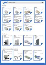
general index Screw terminal connection 10A - 230/400V page 27 Spring terminal connection 10A - 400V from page 28 Crimp connection 10A - 250V from page 39 Screw terminal connection 16A - 250V from page 48 Spring terminal connection 10A - 400V from page 50 SQUICH® connection 16A - 500V from page 60 Screw terminal connection 16A - 500V from page 68 Spring terminal connection 16A - 500V from page 68 Crimp connection 16A - 500V from page 74 Crimp connection 16A - 500V from page 80 Enclosures JEI®-P from page 88 - Metallic - Thermoplastic lever - IP65 from page 102 - Metallic - Galvanised steel lever...
Open the catalog to page 3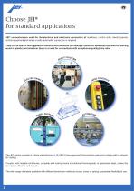
Choose JEI® for standard applications JEI® connectors are used for the electrical and electronic connection of machines, control units, electric panels, control equipment and where a safe sectionable connection is required. They can be used in non-aggressive industrial environments (for example, automatic assembly machines for working wood or plastic) and wherever there is a need for connections with an optimum quality/price ratio. The JEI® series consists of inserts manufactured in UL 94 V-0 type-approved thermoplastic resin and contacts with a galvanic tin coating. Coupling with metallic enclosures,...
Open the catalog to page 4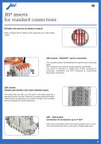
JEI® inserts for standard connections Reliable and precise tin-plated contacts Brass contacts with tin plating which guarantee up to 200 mating cycles. JSH inserts: “SQUICH®” quick connection The innovative solution that eliminates the need for tools in the wiring stage. The connections are made by simply pressing a pushbutton. The result? A reduction in cabling time of 50% compared to screw-type connections and 20% compared to conventional spring-type connections. JDS inserts: Greater pole density in the same standard space The inserts that can offer up to 84 poles in the same space as a standard...
Open the catalog to page 5
The JEI® enclosures make all the difference Select the levering system that best suits your needs Two types of lever to create the best connection: - JEI®-V galvanized steel levers with vertical closure - JEI®-P with levers in thermoplastic material. JEI®-P Thermoplastic Levers JEI®-V Vertical Closing Closing covers in thermoplastic material The enclosures with JEI®-V series levers, in galvanized steel, may be provided with hinged thermoplastic covers. Sizes available: 44.27, 57.27, 77.27, 104.27, 77.62, 104.62
Open the catalog to page 6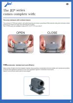
The JEI® series comes complete with: The only enclosure with vertical closure The exclusive V-TYPE lever system, with vertical opening and closure, guarantees IP66 protection rating and minimises mobile enclosure pin friction and wear even with frequent coupling. The V-TYPE levers are available in sizes 44.27, 57.27, 77.27 and 104.27. T-TYPE enclosures: resistant and cost effective Made entirely of highly thick thermoplastic material, they guarantee considerable structural solidity and mechanical durability, combined with significant resistance to the main aggressive agents in industrial environments....
Open the catalog to page 7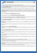
IMPORTANT NOTES ILME designs and manufactures complete solutions for Heavy Duty electrical power connections. The connector (although offered to the user as a variety of elements, usually inserts and enclosures, to allow the selection of the ideal combination) has been designed as complete connector and tested to be compliant with the essential safety requirements of the EU Low Voltage Directive 2006/95/EC and in particular the EN 61984 standard. The design of this “whole” system guarantees that every allowed combination of inserts, enclosures and accessories cannot result as improper. The products...
Open the catalog to page 8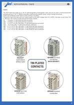
technical features - inserts Inserts The JEI® inserts are made of UL 94 V-0 self-extinguishing thermoplastic resin and can be used in environments with temperatures up to 125 °C. Different termination methods are available: screw, crimp or spring connections. Inserts are numbered on both sides by laser printing or moulding. Choose the insert that best suits your needs based on the rated voltage (from 50 to 500V), the rated current (from 10A to 16A max), the number of poles and the termination method: JK 3-4 poles + m with screw terminal connection JKS 3-4 poles + m with spring terminal connection...
Open the catalog to page 9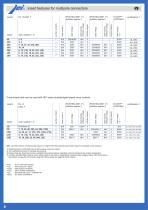
insert features for multipole connectors pollution degree pollution degree rated impulse withstand voltage rated voltage rated impulse withstand voltage auxiliary contacts rated voltage Crimp inserts that may be used with JEI® series tin-plated/gold-plated crimp contacts N.B.: all inserts have a mechanical life equal to or higher than 500 coupling cycles (200 cycles for tin-plated crimp contacts) 1) Polarities shown in brackets may be achieved by using two inserts. 2) The certifications shown in brackets are pending. 3) Please check the insert load curves to establish the actual maximum operating...
Open the catalog to page 10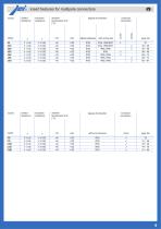
contact resistance insulation resistance ambient temperature limit (°C) without enclosures with enclosures contact resistance insulation resistance ambient temperature limit (°C) conductor connection insert features for multipole connectors conductor connection without enclosures
Open the catalog to page 11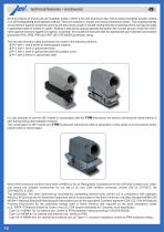
technical features - enclosures Several versions of enclosures are available, made in either a die cast aluminium alloy with an epoxy-polyester powder coating or in self-extinguishing thermoplastic material. They are resistant to impact and strong mechanical stress. The coupling stability and protection against accidental opening are assured by single or double closing devices comprising levers, springs and pegs in galvanised steel or entirely in plastic. Sealing is assured by special gaskets that protect the contact groups inside the enclosures against dust and aggressive agents. In general,...
Open the catalog to page 12All ILME catalogs and technical brochures
 CXCM 4/8
2 Pages
 CX 01 MIF
3 Pages
 CR 03 GKIVGR
2 Pages
 CHC 48 LG
2 Pages
 CR 10 GTPC
2 Pages
 CX 08 D5GF
2 Pages
 General catalogue
772 Pages
 multipole connector 2018
92 Pages
 Multipole connector 2019
140 Pages
 QM - QC
44 Pages
 BK
BK28 Pages
 APV ATEX
23 Pages
 AP-AC
AP-AC13 Pages
 JEI® LEAFLET
8 Pages
 AS
AS32 Pages
 CLASS LEAFLET
8 Pages
 T-TYPE / HYGIENIC
60 Pages
 CN16 - ENCLOSURES
371 Pages
 CN16 - INSERTS
217 Pages
 New 2016 product
60 Pages
 TM
TM60 Pages
 IB6
IB636 Pages
 TM interlocked switched sockets
48 Pages
 CN12
CN12520 Pages
 New 2008-2009
15 Pages
 Jei multipole connectors series
14 Pages



Archived catalogs

- Metal box
- Protection housing
- Custom housing
- Compact housing
- Modular housing
- Built-in box
- Standard box
- IP66 housing
- Stainless steel housing
- IP67 housing
- Surface mounting enclosure
- Connector housing
- Flange enclosure
- EMC-shielded enclosure
- Metal electrical contact
- Alloy enclosure
- Cabinet enclosure
- Metal connector housing
- Connector enclosure