HF547
1 /28Pages

HF547
1 /28Pages
Catalog excerpts

Tank mounted return line filters
Open the catalog to page 1
THE IMPORTANCE OF AN EFFICIENT FILTRATION The main cause of anomalies in hydraulic systems has to be attributed to the presence of contaminants in the fluid. The nature of the contaminant may be: gaseous, namely air mixed with the fluid; fluid, it depends on water penetrating the fluid; solid, therefore particles of various origins and dimensions. Customers who operate equipments are always focused on obtaining the best possible performance, lower energy consumptions and greater respect for the environment. These characteristics can be attained by using top quality components in the hydraulic...
Open the catalog to page 2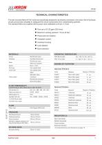
TECHNICAL CHARACTERISTICS The tank mounted filters HF 547 series are specifically designed to be directly connected on the return line of hydraulic circuits and provide versatility to safeguard the circuit components from contaminating particles. The standard filters are supplied with by-pass valve calibrated at 25 psi (1,7 bar). l Flow up to 53 US gpm (200 l/min) l Maximum working pressure 116 psi (8 bar) l Pressurized air breather l Antisplash system l Anodized housing l Level dipstick l Bowl extension MATERIALS OPERATING TEMPERATURE Reinforced nylon With Buna seals Anodized aluminum With Viton...
Open the catalog to page 3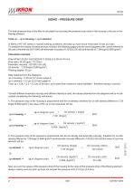
SIZING – PRESSURE DROP The total pressure drop of the filter is calculated by summing the pressure drop value in the housing to the one in the filtering element. Total Dp = Dp in housing + Dp in element In filters of HF 547 series in normal working conditions, the total Dp must not be more than 5.8 psi (0,4 bar). To establish the values of pressure drop involved, the following pages provide some diagrams with curves referred to the use of mineral oils ISO VG46 with kinematic viscosity of 120 SSU (30 cSt) and density of 7.29 lb/gal (0,856 kg/dm3). Calculation example Filter HF547-20.201-AS-FG025-B17-GG-B-S-Z-XN-G-YN-A-K...
Open the catalog to page 4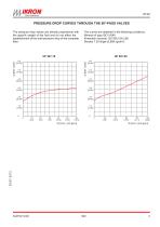
PRESSURE DROP CURVES THROUGH THE BY-PASS VALVES The pressure drop values are directly proportional with the specific weight of the fluid and do not affect the establishment of the total pressure drop of the complete filter. The curves are obtained in the following conditions: Mineral oil type ISO VG46 Kinematic viscosity 120 SSU (30 cSt) Density 7.29 lb/gal (0,856 kg/dm3).
Open the catalog to page 5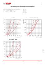
PRESSURE DROP CURVES THROUGH THE HOUSING (1) G 3/8 (2) G 1/2 (3) G 3/4 (4) G 1 (5) G 1 1/4 The curves are obtained in the following conditions: Mineral oil type ISO VG46 Kinematic viscosity 120 SSU (30 cSt) Density 7.29 lb/gal (0,856 kg/dm3).
Open the catalog to page 6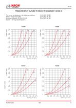
PRESSURE DROP CURVES THROUGH THE ELEMENT HEK02-08 (1) HE K02-08.095 (2) HE K02-08.145 (3) HE K02-08.195 The curves are obtained in the following conditions: Mineral oil type ISO VG46 Kinematic viscosity 120 SSU (30 cSt) Density 7.29 lb/gal (0,856 kg/dm3).
Open the catalog to page 7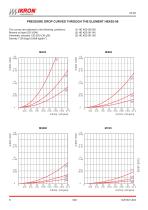
PRESSURE DROP CURVES THROUGH THE ELEMENT HEK02-08 (1) HE K02-08.095 (2) HE K02-08.145 (3) HE K02-08.195 The curves are obtained in the following conditions: Mineral oil type ISO VG46 Kinematic viscosity 120 SSU (30 cSt) Density 7.29 lb/gal (0,856 kg/dm3).
Open the catalog to page 8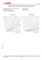
PRESSURE DROP CURVES THROUGH THE ELEMENT HEK02-08 (1) HE K02-08.095 (2) HE K02-08.145 (3) HE K02-08.195 The curves are obtained in the following conditions: Mineral oil type ISO VG46 Kinematic viscosity 120 SSU (30 cSt) Density 7.29 lb/gal (0,856 kg/dm3).
Open the catalog to page 9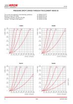
PRESSURE DROP CURVES THROUGH THE ELEMENT HEK02-20 The curves are obtained in the following conditions: Mineral oil type ISO VG46 Kinematic viscosity 120 SSU (30 cSt) Density 7.29 lb/gal (0,856 kg/dm3).
Open the catalog to page 10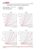
PRESSURE DROP CURVES THROUGH THE ELEMENT HEK02-20 The curves are obtained in the following conditions: Mineral oil type ISO VG46 Kinematic viscosity 120 SSU (30 cSt) Density 7.29 lb/gal (0,856 kg/dm3).
Open the catalog to page 11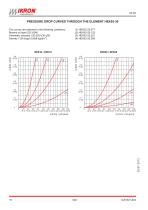
PRESSURE DROP CURVES THROUGH THE ELEMENT HEK02-20 The curves are obtained in the following conditions: Mineral oil type ISO VG46 Kinematic viscosity 120 SSU (30 cSt) Density 7.29 lb/gal (0,856 kg/dm3).
Open the catalog to page 12
MICRO-FIBRE GLASS FLOWS Degree of filtration FG003 Flow Dp= 5.8 psi (0,4 bar) ("AS" version values) Filter type
Open the catalog to page 13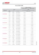
CELLULOSE FLOWS Degree of filtration RP010 / SP010 Filter type
Open the catalog to page 14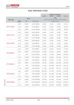
STEEL WIRE MESH FLOWS Degree of filtration MI025 Flow Dp= 5.8 psi (0,4 bar) ("AS" version values) Filter type
Open the catalog to page 15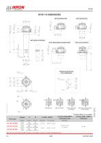
HF547-10 DIMENSIONS WITH AIR BREATHER WITH ANTISPLASH WITH BOWL EXTENSION WITH PRESSURIZED AIR BREATHER WITH LEVEL DIPSTICK RESERVOIR MOUNTING HOLE DIMENSIONS With By-pass With pressurized air breather With pressurized breather and air suction * Antifoam diffusers are available. Weight Filter type (1)(2)(3) (GAS-BSPP) Secondary inlet Standard NPT, metric and SAE UN-UNF threads are available (consult our technical department).
Open the catalog to page 16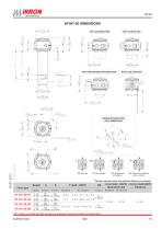
HF547-20 DIMENSIONS WITH AIR BREATHER WITH ANTISPLASH WITH PRESSURIZED AIR BREATHER WITH LEVEL DIPSTICK RESERVOIR MOUNTING HOLE DIMENSIONS With By-pass With pressurized air breather With pressurized breather and air suction * Flexible extension bowls and antifoam diffusers are available. Weight Filter type Standard (3)(4) (GAS - BSPP) (1)(2)(3) (GAS-BSPP) Secondary inlet Indicators Standard NPT, metric and SAE UN-UNF threads are available (consult our technical department).
Open the catalog to page 17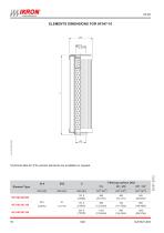
Element Type Technical data for (FS) version elements are available on request.
Open the catalog to page 18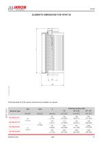
Technical data for (FS) version elements are available on request. Element type
Open the catalog to page 19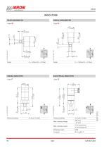
INDICATORS REAR MANOMETER Code: RADIAL MANOMETER VISUAL INDICATOR Code: ELECTRICAL INDICATOR Pressure setting Pressure setting Max. working voltage Max. working current Protection class
Open the catalog to page 20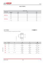
INLET PORTS PORTS TYPE Filter type Nominal size Cylindrical GAS thread (55°) in accordance with UNI - ISO 228 Nominal size
Open the catalog to page 21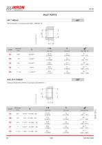
INLET PORTS NPT THREAD NPT thread (60°) in accordance with ANSI - ASME B1-20 Nominal size Nominal size American thread UNC-UNF 60° in accordance with
Open the catalog to page 22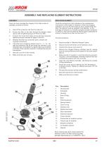
ASSEMBLY AND REPLACING ELEMENT INSTRUCTIONS ASSEMBLY REPLACING ELEMENT Once you have checked the integrity of the filter inside its package, proceed as follows: A Take off the protection cap from the inlet port. Ensure the filter to the tank through the flange's holes (pos.3) with a tightening torque of 44 lbf in (5 Nm). Once the working hour limit indicated in the manteinance instructions of the system is reached or when the clogging indicators point out the limit pressure drop created inside the filter, the element must be replaced. Pay attention to the drainage of hydraulic oil, therefore...
Open the catalog to page 23All Ikron catalogs and technical brochures
 IKRON FLUX OIL
5 Pages
 HL98
HL984 Pages
 HF690
HF69010 Pages
 HF532
HF53212 Pages
 HF 502 / HF 508 series
44 Pages
 HF431/434/437
4 Pages
 HF 410 / HF 412 series
20 Pages