
Catalog excerpts

Precision Positioning Table TU Ball screw Slide table with high accuracy and high rigidity in a single structure Compact and slim type positioning table with an original U-shaped track rail Page -33 The optimal table specification can be selected from a variety of options Ball screw The optimal positioning table for each specific application can be configured easily by only indicating required functions and performance from our substantial size variations and a variety of options by the identification number. Track rail Variation Linear Way Shape Standard Track rail widthmm 25 Short table...
Open the catalog to page 2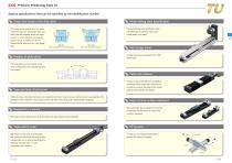
Precision Positioning Table TU Special specifications that can be specified by the identification number Motor folding back specification Shape and length of the slide table The shape can be selected from two types, The motor folding back specification table "standard" type and "with flange" type, and can realize space saving by reducing the three types with different length with same overall length of the table. section, i.e. short, standard, and long are listed on lineup. A bridge cover and XY bracket can be attached to the "with flange" type. Standard Short (C), standard (no symbol), long (G)...
Open the catalog to page 3
Shape of slide table Length of track rail Designation of motor attachment Ball screw type Shape of slide table TU: Precision Positioning Table TU Size indicates bed width. Select a size from the list of Table 1. Short table Standard table Long table Flange type short table Flange type standard table Flange type long table Table 1 Application of shape of slide table Example of an Identification Number Identification Number and Specification Ball screw lead Number of slide table Cover specification Length of track rail From the [Identification] of track rail length shown in Table 2.1 and 2.2,...
Open the catalog to page 4
Identification Number and Specification Designation of motor attachment Motor inline specification Motor inline specification Motor folding back specification Motor folding back specification Without motor attachment With motor attachment Without motor attachment With motor attachment Cover specification When specifying "With bellows (J)", select 1 piece (by specifying S) for the entry of section 8. "With bellows" type is not provided for TU60 with track rail lengths of 990 and 1,190mm and TU86 with track rail lengths of 1,390 and 1,590mm. "With bridge cover" type is not provided for TU60 with...
Open the catalog to page 5
Identification Number and Specification Table 6.1 Application of motor attachment (motor inline specification) Remark: For detailed coupling specification, please see respective manufacturer's catalog.
Open the catalog to page 6
Table 8.1 TU accuracy (rolled screw) unit: mm Remark: To measure the practical maximum speed, it is required to consider operation patterns based on the motor to be used and load
Open the catalog to page 7
Table 10 Maximum carrying mass Note (1) In directions indicated in the above figures, the value in ( ) is for two slide tables in close contact.
Open the catalog to page 8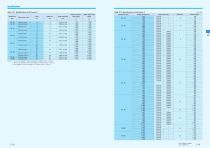
Specifications Table 12.1 Specifications of ball screw 1 Model and size TU 25 TU 30 Ball screw type Ground screw Ground screw Table 12.2 Specifications of ball screw 2 Shaft dia. mm 0.005 or less 0.005 or less 0.05 or less 0.005 or less 0.05 or less 0.005 or less 0.05 or less 0.005 or less 0.05 or less 0.005 or less 0.005 or less 0.005 or less 0.005 or less unit: mm Ball screw type Ground Ground Ground Ground Ground Ground Ground Ground Ground Ground Rolled Ground Rolled Ground Rolled Ground Rolled Ground Rolled Ground Rolled Ground Rolled Ground Rolled Ground Rolled Ground Rolled Ground...
Open the catalog to page 9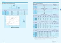
Specifications Table 13 Moment of inertia of sectional area of track rails Table 14.1 Table inertia and starting torque Table inertia JT Length Model and of track rail size mm Short table Standard table Lead 4mm Model Length and of track rail size mm Fig. 1 Deflection vs. Downward load Short table Standard table Short table Starting torque TS N m Rolled screw Ground screw Long table Ground screw Standard table Long table Rolled screw Model Length and of track rail size mm Long table Ground screw Model Length and of track rail size mm Standard table Moment of inertia of sectional area mm4...
Open the catalog to page 10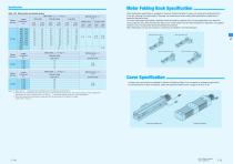
Motor Folding Back Specification Specifications Table 14.2 Table inertia and starting torque Table inertia JT Model and size Short table Standard table Long table Rolled screw Ground screw Motor folding back specification is available for Precision Positioning Table TU, space can be saved by folding back the motor and reducing the overall length of the table. For dimensions of motor folding back specification, please refer to respective dimension table. For motor folding back specification, assembly should be made by customer since "housing applicable to the specified motor, pulley (on motor side...
Open the catalog to page 11
Two Slide Table Specification Sensor Specification Two slide table specification is available for Precision Positioning Table TU. Ball screw nuts are mounted on slide table at the motor side, and it can be driven by the motor (driving table). Ball screw nuts are not mounted on slide table at the opposite motor side, and it is free condition (driven table). It is possible to make the structure resistant to moment load by using two slide tables in combination (Table 11). When combining slide tables, allow more clearance than "minimum center distance between two slide tables in close contact" 63...
Open the catalog to page 12
Sensor Specification Table 15.2 Sensor timing chart (motor folding back specification) Table 15.3 Sensor timing chart (motor inline specification, with C-Lube) Length of slide table Short unit: mm Model and size * In a table of motor folding back specification, the movements of CW direction and CCW direction in a slide table become reversed. Ball screw lead Mechanical stopper Length of slide table Mechanical stopper Stroke length Standard Long Ball screw lead 4 Standard Long The value in ( ) indicates the dimension for two slide tables. After pre-origin signal is turned off, CCW limit is turned...
Open the catalog to page 13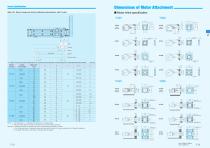
Dimensions of Motor Attachment Sensor Specification Motor inline specification Table 15.4 Sensor timing chart (motor folding back specification, with C-Lube) (without attachment) Stroke length (without attachment) 4-3.4 Through 6.5 Counterbore depth 6.5 4-3.4 Through 6.5 Counterbore depth 6.5 4-3.4 Through 6.5 Counterbore depth 6.5 4-3.4 Through 6.5 Counterbore depth 6.5 4-3.4 Through 6.5 Counterbore depth 3.3 4-3.4 Through 6.5 Counterbore depth 3.3 4-M3 Through PCD45, Evenly distributed at 90° 4-M3 Through PCD45, Evenly distributed at 90° 4-M4 Through PCD46, Evenly distributed at 90° 4-M4...
Open the catalog to page 14All IKO Nippon Thompson Europe catalogs and technical brochures
-
 Programmable Controller
2 Pages
-
 BSP/BSPG/BSR
14 Pages
-
 MV
MV6 Pages
-
 Cam Followers: CAT-1563E
31 Pages
-
 CG2?CGL
2 Pages
-
 AF2
AF22 Pages
-
 Linear Motion Rolling Guide
13 Pages
-
 New Products
16 Pages
-
 C-Lube Linear Way MLV
6 Pages
-
 C-Lube Linear Way V
8 Pages
-
 Cam Followers
33 Pages
-
 IKO C-lube linear portfolio
21 Pages
-
 2011 New Product Guide
12 Pages
-
 Linear Motion Guide Series
392 Pages
-
 Needle Bearing Series
308 Pages


Archived catalogs
-
 Linear Roller Way Super X
20 Pages
-
 C-Sleeve Linear Way
25 Pages
-
 Linear Ball Spline G
32 Pages
