SP209
1 /23Pages

SP209
1 /23Pages
Catalog excerpts
SP209 series datasheet and user manual SP209 and SP209i 9 channels, 200 MSPS logic analyzer with industrial inputs option
Open the catalog to page 1
SP209 Series User Manual Contents SP209 Series overview Typical applications . . . . . . . . . . . . . . . . . . . . . . . . . . . . . . . . . . . . . . . Product highlights . . . . . . . . . . . . . . . . . . . . . . . . . . . . . . . . . . . . . . . . Main characteristics Operating conditions . . . Timing and measurements Logic inputs specifications Power requirements . . . Principle of operation Embedded memory vs streaming . . . . Versatile trigger system . . . . . . . . . . External trigger OUT specifications External trigger IN specifications . . Industrial port (SP209i only) RS485 receiver...
Open the catalog to page 2
SP209 Series User Manual Ordering information and customer support Safety information Symbols definitions . . . . . . . . . . . . . . . . . . . . . . . . . . . . . . . . . . . . . . . Important safety notes . . . . . . . . . . . . . . . . . . . . . . . . . . . . . . . . . . . . . . Limited warranty & limitation of liability Document Revisions
Open the catalog to page 3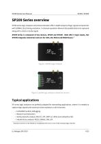
SP209 Series User Manual SP209 Series overview SP209 series logic analyzers and protocol decoders offer in depth analysis of logic signals and protocols with 200MHz (5ns) timing resolution. 9-channel operation allows 8-bit parallel data to be captured along with a clock or strobe signal. SP209 Series is composed of two devices, SP209 and SP209i. Both offer 9 logic inputs, but SP209i integrates industrial receivers for CAN, LIN, RS232 and RS485 buses.1 Figure 1: SP209 Logic Analyzer Figure 2: sp209i logic analyzer (industrial version) Typical applications SP series logic analyzers are perfectly...
Open the catalog to page 4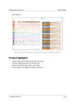
SP209 Series User Manual Figure 3: Example of logic signals captured and analyzed by SP209 logic analyzer Product highlights • • • • Schmitt trigger input stages with adjustable thresholds 200 MHz sampling rate, with all 9 channels used. External clock option (state mode), up to 50MHz Precise trigger-In and trigger-Out signals on SMA ports
Open the catalog to page 5
SP209 Series User Manual Warning Read safety information section carefully before using this instrument.
Open the catalog to page 6
SP209 Series User Manual Main characteristics Operating conditions Temperature Relative humidity Timing and measurements2 Sampling rate (MAX.) External clock Max rate (State mode) Logic Inputs digital bandwidth Embedded memory Trigger output External trigger input Logic inputs specifications Number of channels Input impedance Threshold circuits Adjustable logic level (for each threshold) Absolute max voltage on digital inputs (Continuous or Transient) Power requirements Input power connector Input current DDR-3 sampling memory is used to buffer samples before streaming to host computer.
Open the catalog to page 7
SP209 Series User Manual Input voltage SP209(i) Interfaces SP209(i) logic analyzer ports and interfaces are shown in the diagram below: Status LED 9-CH logic probes input Trigger OUT SMA connector Trigger IN SMA connector USB (micro-B) port. Industrial port 3 Only on SP209i (industrial) version.
Open the catalog to page 8
SP209 Series User Manual Principle of operation SP209 Series logic analyzers connects to a computer via a USB cable. A free software - called ScanaStudio - is used to configure the device and display captured signals. The software can also be used to further analyze the captured samples by decoding protocols like I2C, SPI or UART. Embedded memory vs streaming USB based logic analyzers (ones that don’t have a display and rely on a computer for that matter) usually operate according to one of two schemes: • Using an embedded memory to store captured samples. Samples are later downloaded at a slower...
Open the catalog to page 9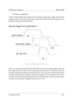
SP209 Series User Manual • A or B (whoever triggers first) Finally, an external trigger output is always active, in all modes and generates a trigger pulse whenever a trigger condition is met and a capture starts. Signal specifications for External trigger input and output are detailed in the following section. External trigger OUT specifications Figure 5: External trigger OUT timings There is an internal data path delay of 20ns before external signals reach internal trigger engine (T0). When trigger event occurs, 10ms (T2) pulse is generated on the Trig Out port. This port has a 50 Ωseries impedance...
Open the catalog to page 10
SP209 Series User Manual External trigger IN specifications Figure 6: External trigger IN timings The Trig In port allows to start acquisition on an external event generated by another instrument. The minimum pulse width (T1) is 5ns. Polarity can be set in software. The input impedance is also software selectable (100k Ωor 50 Ω). The threshold level is 1.0V. T2, the time between external trigger in active edge and internal trigger engine assertion is 20ns. Industrial port (SP209i only) SP209i offer the possibility to connect directly to industrial buses, as opposed to logic channels which can...
Open the catalog to page 11
SP209 Series User Manual • LIN bus receiver Please refer to the marking on SP209i casing for exact pinout. RS485 receiver specifications Transceiver MPN Maximum baudrate Common Mode Operating range Common Mode Input Impedance Common Mode voltage (absolute maximum) Differential Threshold voltage Differential Fixed hysteresis Differential Input Impedance RS232 receiver specifications Transceiver MPN Operating range Input Impedance Threshold voltage CAN receiver specifications Transceiver MPN Common Mode Operating range
Open the catalog to page 12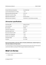
SP209 Series User Manual Common Mode Input Impedance Common Mode Absolute max voltage Differential Mode Operating range Differential Threshold voltage Differential Fixed hysteresis Differential Input Impedance 25 kΩ|| 20 pF or 120 ΩSoftware selectable LIN receiver specifications Transceiver MPN Main specification Threshold voltage Please note that SP209i can still only capture 9 channels simultaneously. Industrial inputs are internally multiplexed with logic inputs. It is recommended to connect the ground of the industrial bus being measured to the nearest ground screw terminal (Refer to marking...
Open the catalog to page 13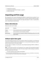
SP209 Series User Manual 2. USB cable (micro-B to A) 3. 10 leads hook-style probes set (9 signals + 1 ground) 4. SMA anti-dust covers Unpacking and first usage We recommend the user to start by identifying all the different components that are provided. To turn ON the SP209 device, connect it to a free USB port of your computer using the provided USB cable5 . The LED should glow according to the table in the “Status LEDs behavior” section. To switch off the device, simply disconnect the USB cable. Status LEDs behavior Status led can be in one of 3 states: Status LED Device powered up but not connected...
Open the catalog to page 14All IKALOGIC catalogs and technical brochures
 SP1000G series
26 Pages
 IkaScope WS200
21 Pages