SP1000G series
1 /26Pages

SP1000G series
1 /26Pages
Catalog excerpts
SP1000G series datasheet and user manual 1GSPS logic analyzer and pattern generator
Open the catalog to page 1
SP1000G Series User Manual Contents SP1000G Series overview Typical applications . . . . . . . . . . . . . . . . . . . . . . . . . . . . . . . . . . . . . . . Product highlights . . . . . . . . . . . . . . . . . . . . . . . . . . . . . . . . . . . . . . . . Main characteristics Operating conditions . . . . . . . . . . . . . Timing and measurements . . . . . . . . . . Active probes set specifications (input mode) Power requirements . . . . . . . . . . . . . SP1000G Interfaces SP1018G host device interfaces . . . . . . . . . . . . . . . . . . . . . . . . . . . . . . . . . Active probe set interfaces...
Open the catalog to page 2
SP1000G Series User Manual Mechanical data Host device model SP1018G . . . . . . . . . . . . . . . . . . . . . . . . . . . . . . . . . . . Active probe set . . . . . . . . . . . . . . . . . . . . . . . . . . . . . . . . . . . . . . . . . . Probes terminations . . . . . . . . . . . . . . . . . . . . . . . . . . . . . . . . . . . . . . . Software technical requirements Ordering information Accessories, maintenance and customer support Safety information Symbols definitions . . . . . . . . . . . . . . . . . . . . . . . . . . . . . . . . . . . . . . . Important safety notes . . . . . . . . . . . ....
Open the catalog to page 3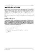
SP1000G Series User Manual SP1000G Series overview SP1018G series logic analyzers and pattern generators offer in depth analysis of logic signals and protocols with 1GSPS (1ns) timing resolution. External reference clocking (IN and OUT), trigger input and output as well as adjustable threshold and output voltage level make SP1000G series a uniquely powerful laboratory equipment. SP1000G series offer up to 54 channels that can be individually configured as input, push-pull outputs or open drain output. Please refer to ordering information for the exact number of available channels and embedded...
Open the catalog to page 4
SP1000G Series User Manual Figure 1: Example of logic signals captured and analyzed by SP1018G logic analyzer Product highlights • Schmitt trigger input stages with adjustable thresholds (each group of 9 channels can have a different input threshold). • 1 GSPS capture rate (adjustable down to 4 MSPS) • Embedded buffer memory (4Gb, 8Gb or 12Gb depending on model). • USB3 super-speed interface. • Samples compression (only events consume memory and USB bandwidth). • Various trigger options (Edge, pulse width, pattern, protocol). • Two independent trigger engines that can be combined to create cascaded...
Open the catalog to page 5
SP1000G Series User Manual Warning Read safety information section carefully before using this instrument.
Open the catalog to page 6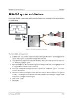
SP1000G Series User Manual SP1000G system architecture A functional SP1000G measurement system consists of several main components that are presented in the image below. Figure 2: SP1000G system architecture The main labeled components are: 1. SP1000G main host unit that contains the main memory buffer and the processing power to capture and compress signals before sending them over USB. 2. Computer running ScanaStudio software (Windows / Mac / Linux) that controls the main host unit and display captured signals. 3. Probes to host harness (60 cm): Flexible, high speed (10Gbps) LVDS cable, allowing...
Open the catalog to page 7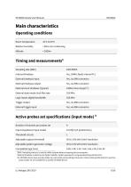
SP1000G Series User Manual Main characteristics Operating conditions Room Temperature Relative humidity Timing and measurements1 Sampling rate (MAX.) Internal timebase External timebase input External timebase output External clock timebase (Typical) External state mode clock Max rate Logic Inputs digital bandwidth Trigger output External trigger input Active probes set specifications (input mode) 3 Number of channels per probes set Input impedance (Input mode) Threshold circuits Adjustable capture threshold Adjustable pattern generator voltage Compatible logic level DDR-3 sampling memory is used...
Open the catalog to page 8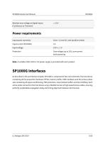
SP1000G Series User Manual Absolute max voltage on digital inputs (Continuous or Transient) Power requirements Input power connector 5mm / 2.1mm DC Jack (positive center) Input voltage Overvoltage (up to 25V), overcurrent, back-powering. Note: A suitable 220V/110V to 12V power supply is provided with each product. SP1000G Interfaces As described in the architecture chapter, SP1018G is composed of two main elements, the host device containing all the acquisition hardware (FPGA, memory buffer, USB interfaces) and the active probes sets containing all signal conditioning, ESD protection, Input/Output...
Open the catalog to page 9
SP1000G Series User Manual SP1018G host device interfaces 12V DC power input USB3 port (Type B) 3 Earth connection (M3 thread size) 10MHz Reference clock input (optional) - 50 Ohm impedance Trigger input - 50 Ohm impedance Reference clock output Trigger clock output Status LED Port A (connection to 9-channels active probe set) Port B (connection to 9-channels active probe set)
Open the catalog to page 10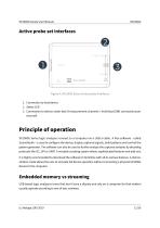
SP1000G Series User Manual Active probe set interfaces Figure 4: SP1000G Series Active probe interfaces 1. Connection to host device 2. Status LED 3. Connection to device under test (9 measurement channels + individual GND connections per channel) Principle of operation SP1000G Series logic analyzers connect to a computer via a USB-3 cable. A free software - called ScanaStudio - is used to configure the device, display captured signals, build patterns and control the pattern generator. The software can also be used to further analyze the captured samples by decoding protocols like I2C, SPI or...
Open the catalog to page 11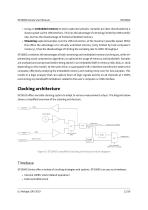
SP1000G Series User Manual • Using an embedded memory to store captured samples. Samples are later downloaded at a slower speed via the USB interface. This has the advantage of not being limited by USB transfer rate, but has the disadvantage of limited embedded memory. • Streaming captured samples over the USB connection, at the maximum possible speed. While this offers the advantage of a virtually unlimited memory (only limited by host computer’s memory), it has the disadvantage of limiting the sampling rate to USB’s throughput. SP1000G combines the advantages of both streaming and embedded...
Open the catalog to page 12All IKALOGIC catalogs and technical brochures
 SP209
SP20923 Pages
 IkaScope WS200
21 Pages