- Catalogs
- IEF-Werner GmbH
- Guides and Slides
- Company
- Products
- Catalogs
- News & Trends
- Exhibitions
Guides and Slides
1 /42Pages

Guides and Slides
1 /42Pages
Catalog excerpts

__I Longitudinal Guides Page What you should know... -4 Type R + K; roller, ball, smooth-running for optimum precision _ 6 Type N/O; needle rollers for heavy loads_ 10 Type M/V; plastic coating, for high damping_12 Calculation for the anti-friction slideways _16 Calculation for the standard slideways- - 17 What you should know...- - 21 Type O; open design- -22 Type M; with spindle and micrometer-26 Type H; with spindle and hand crank- - 28 With built-in cylinder - -40 Type RGA with scraper and baseplate- — 41 DOMINO - the adjustment slide system— - 42
Open the catalog to page 3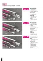
Longitudinal guides Main characteristics: Smooth running l Low friction coefficient l Long service life l Maximum precision and rigidity thanks to pretensioning l Low maintenance l No stick-slip effect Areas of use: l Measuring and testing equipment l Closed-loop control systems l Precision mechanical engineering Main characteristics: Smooth running l Low friction coefficient (under normal conditions µr = 0.003) l Long service life l No stick-slip effect l Maximum precision and rigidity thanks to pretensioning l Low maintenance l Very high load-bearing capacity Areas of use: l Processing machines...
Open the catalog to page 4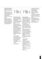
What you should know... In technology, a distinction is generally made between rotary and translatory movements. Translatory movements are normally performed in practice by longitudinal guides. Longitudinal guides are used in large numbers for positioning work in mechanical engineering and handling systems. Various guide systems are available, depending on operational requirements and the main property of the application. Guide systems are generally classified as anti- friction slideways and standard slideways. Anti-friction slideways In all anti-friction slideways, the longitudinal guides are...
Open the catalog to page 5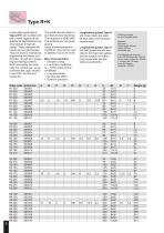
Type R+K Cross-roller guide rails of Types R+K can be fitted with ball or roller cages and are suitable for applications involving medium to high demands. These standard elements can be interchanged. They are used in mechanical engineering and fixture construction, as well as in measuring and testing systems. Both horizontally and vertically. For vertical use, we recommend the cage variants V and HVK, and the end screws EV. The guide rails are made of tool steel and are hardened. The hardness is 60-62 HRC. The surfaces are very finely ground. Under normal operational conditions, they can be used...
Open the catalog to page 6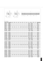
Ball / roller guide
Open the catalog to page 7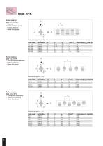
Type R+K Roller retainer type R-1...9 HVK l Suitable for all installation types l Rollers retained l Made from plastic Roller retainer type R-1...9 HVK Roller retainer type R-3...12 H l For horizontal installation l Rollers retained l Made from steel Roller retainer type R-3...12 H Roller retainer type R-3...18 V l For vertical installation l Rollers not retained l Made from brass Load rating Cdyn/roller [N] 130 530 1300 2500 Roller retainer type R-3...18 V
Open the catalog to page 8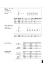
Ball cage Type K-1...12 HVK l Suitable for all installation types l Balls held l Material plastic, from size 6 in compound design plastic/steel Ball cage Type K-15...24 V For all installation types, apart from over-running cages l Balls not held l Material plastic/brass End screws Type EH for balls + rollers, installation horizontal. O End screws Type EV for balls + rollers, installation vertical. O Load rating Cdyn/roller [N] 410 600
Open the catalog to page 9
Type N/O Needle roller guide rails of the Type N/O are suitable for applications in which the stress is very high and/or when very short strokes have to be travelled. They are best used in mechanical engineering and also in machine tools and processing machines. They can be used both horizontally and vertically. Due to "roll friction", the linear guides function almost wear-free. The guide rails are made of tool steel and are har-dened. The hardness is around 60-62 HRC. The surfaces are finely ground. Under normal conditions, they can be used at speeds of up to 50 m/min. In order to achieve maximum...
Open the catalog to page 10
Type M/V Plastic-coated guides Type M/V are standard slideways. They are mainly suitable for applications in which high transverse forces and transverse accelerations, vibrations and impacts occur. They are also for highfrequen-cy, extremely short strokes. Normally, no anti-friction slideways can be used here, because these cause impressions or result in pit formation on the running surface. These guides are preferably used in machines and equipment construction. They can be used both horizontally and vertically. The V rail is made of tool steel and is hardened and ground. The hardness is around...
Open the catalog to page 12
Plastic-coated guide
Open the catalog to page 13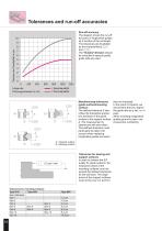
Tolerances and run-off accuracies Run-off accuracy The diagram shows the run-off accuracy of longitudinal guides as a function of the rail length. The tolerances are illustrated A by the characteristics B . and The "Guides" Division should be consulted if special-quality guide rails are used. A = Support surface B = Bearing surface Tolerances for bearing and support surfaces In order to achieve the IEF quality for guide systems, the measured values of the mounting surfaces must not exceed the defined tolerances for the rail sizes. The angle errors of the support surfaces must not be over 0.3...
Open the catalog to page 14
Installation instructions values of the run-off accuracy of the longitudinal guide. l Mounting the longitudinal guide, Figure 2 (II): Tighten the fastening screws only lightly. l When inserting the cages with the rolling elements, Figure 2 (III), into the prefitted longitudinal guides, particular attention must be paid to ensure that the cages do not project when the longitudinal guides are in their end position. l For every fastening screw, insert an adjustment screw, l If possible, all fastening Figure 2 (IV) into the slide holes in the support surfaces, section. The threaded holes Figure 1...
Open the catalog to page 15
Calculation for the anti-friction slideways Type R+K, N/O The dimensioning of longitudinal guides is significantly influenced by the load and stroke parameters. The rail size, rail length and number of rolling elements are calculated from this. The mean spacing of the rails (cage spacing) KA should not be greater than the supporting length of the longitudinal guide (cage length) KL. The purpose of the task is to keep the rolling elements at a defined spacing. This spacing is designated pitch T below. The pitch T of the various rolling elements and also the sizes can be found in the table on Page...
Open the catalog to page 16All IEF-Werner GmbH catalogs and technical brochures
 Spindle drives
64 Pages
 Product overview
60 Pages
 Swivel arm units
24 Pages
 Control technology
20 Pages
 Wheel Gauging System R2010
9 Pages
 posyART transport systems
26 Pages
 Cantilever axes
70 Pages
 Toothed belt drives
76 Pages
 Palletising systems
56 Pages
 Direct drives
56 Pages
 Conveyor system posyART
28 Pages
 Innovations
36 Pages
 Manual adjuster domiLINE
56 Pages

Archived catalogs
 Positioning systems
36 Pages
 Levelling elements
4 Pages
 Cantilever axes Module 68
38 Pages
 DT 80/100
48 Pages


- Industrial press
- Actuator
- Forming press
- Automation software solution
- Linear actuator
- Electric actuator
- Positioning table
- Measuring machine
- Process software
- Windows software
- Control software
- Translation stage
- Automatic press
- Interface software
- Joining press
- Turntable
- Precision positioning table
- Electric rotary table
- Electric press
- Industrial actuator