
- Catalogs
- Idem Safety Switches
- Guardian Line Series


- Products
- Catalogs
- News & Trends
- Exhibitions
Guardian Line Series

Guardian Line Series
Catalog excerpts

Safety Rope Switches from IDEM Data Sheet Heavy Duty Types: GLHD (Dual Head) GLHD-SS (Dual Head) GLHR/L (Single Head) GLHR/L-SS (Single Head) Guardian Line Series Standard Duty Types: GLS GLS-SS Mini Duty Type: GLM GLM-SS Using Safety Rope Emergency Stop Switches Application: Safety Rope Emergency Stop Switches are mounted on machines and sections of plant conveyors which cannot be protected by guards. In contrast to traditional mushroom head type Emergency Stop buttons, Safety Rope Switches can initiate the emergency command from any point along the installed rope length. In combination with any dual channel safety monitoring controllers IDEM Safety Rope Systems can be used as emergency stop devices and monitored for up to Category PLe/Cat.4 to ISO13849-1. It is the responsibility of the user to ensure the correct overall functionality of its systems and machines. IDEM, its subsidiaries and affiliates, are not in a position to guarantee all of the characteristics of a given system or product not designed by IDEM. Operation: All IDEM Safety Rope Emergency Stop Switches conform to Standards ISO13850 and IEC60947-5-5. They have a positive mechanical linkage between the switch contacts and the wire rope as per IEC60947-5-1. The emergency stop switches are brought into the operational condition by pre-tensioning the rope by use of a tensioner/gripper device which clamps the rope and then hooks to the switch eyebolts. Correct tension can be observed by viewing the tension indicator on the switch housing. Once tensioned the switch contact blocks can be set to the operational condition (safety contacts closed, auxiliary contacts open) by pressing a blue reset button on the switch cover. All of the Safety Rope Switches have wire-breakage monitoring. On pulling or breakage (tension loss) of the rope, the safety contacts are positively opened and the auxiliary contacts are closed. The switches are mechanically latched and can then only be returned to the operating condition by pressing the reset button as required by ISO13850. Installation Guide: 1. Installation of all IDEM Safety Rope Switch systems must be in accordance with a risk assessment for the individual application. Installation must only be carried out by competent personnel and in accordance with these instructions. 2. According to ISO13850 pulleys may only be mounted such that a complete length of the rope can be observed. 3. Rope support eyebolts must be fitted at 2.5 m. min. to 3m. max. intervals along all rope lengths between switches. The rope must be supported no more than 500mm from the Switch eyebolt or Safety Spring (if used). It is important that this first 500mm is not used as part of the active protection coverage. 4. M5 mounting bolts must be used to fix the switches. Tightening torque for mounting bolts to ensure reliable fixing is 4 Nm. Tightening torque for the lid screws, conduit entry plugs and cable glands must be 1.5 Nm to ensure IP seal. Only use the correct size gland for the conduit entry and cable outside diameter. 5. Tensioning of rope is achieved by use of IDEM tensioner/gripper assemblies. On installation set the tension to the mid position as indicated by the markers in the viewing window of each switch. Check operation of all switches and the control circuits by pulling the rope at various locations along the active protection area and resetting each switch by depressing the Blue Reset button. Ensure each time that the switches latch off and require manual resetting by depressing the blue reset button. Increase the system tension further, if required, depending upon the checks along the active length of coverage. If fitted with a Mushroom type E-Stop button (Red) then test and reset each switch to ensure correct function of the safety control circuits. Typical operational condition for successful operation of the system is less than 75N. pulling force and less than 150mm deflection of rope between eyebolt supports. 6. Maintenance: Every Month: Check correct operation of system at locations along all coverage length. Check for nominal tension setting, re-tension rope if necessary. Every 6 Months: Isolate power and remove cover. Check screw terminal tightness and check for signs of moisture ingress. Never attempt to repair any switch. Original Instructions. To request this data sheet in other languages please contact [email protected] Um dieses Datenblatt in Deutscher Sprache wenden Sie sich bitte anfordern [email protected] Pour obtenir cette fiche en Français, veuillez contacter [email protected] Para solicitar esta hoja de datos en Español, por favor contacto con [email protected] WARNING: DO NOT DEFEAT, TAMPER, OR BYPASS THE SAFETY FUNCTION. FAILURE TO DO SO CAN RESULT IN DEATH OR SERIOUS INJURY. AVERTISSMENT: NE PAS DESACTIVER, MODIFIER, RETIRER, OU CONTOURNER CETI INTERVERROUILLAGE IL PEUT EN RESULTER DES BLESSURES GRAVES DU PERSONNEL UTILISATEUR.
Open the catalog to page 1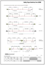
7. Recommended rope span options and fittings - (subject to an individual risk assessment for the installation): GLM 30m. with Safety Spring GLHD 200m. with Safety Springs Contact open Contact closed 0mm 3.5mm 14.5mm 17.0mm Typical operating conditions:
Open the catalog to page 2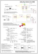
Safety Rope Switches from IDEM (GLH shown) 8. Wiring examples: LED RED Flashing or Steady: Stopped LED GREEN Steady: Run Terminal 3 When power is applied to the Red wire, the lamp will illuminate Red. When power is applied to the Green Wire, the Lamp will illuminate Green. Black is 0V.dc or Neutral for 110Vac and 230Vac versions. (GLS / GLM shown) Optional ASi Safe versions: AS-I profile : S-7.B.E ID configuration / ID code : 7(Hex) / B.E(Hex) 9. To fit Mushroom type Emergency stop Buttons: a) Remove M12 threaded plug from the mounting port. b) Apply thread locking solution to the threads of...
Open the catalog to page 3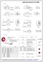
Sales Number Galvanised Stainless Steel Quick Link (QL) For up to 50m. spans ,one rope end is terminated with a thimble and permanent clamp. For over 50m. spans, 2 Tensioner / Gripper assemblies are supplied (no Quick Link). IDEM SAFETY SWITCHES Ltd., 2 Ormside Close, Hindley Industrial Estate, Hindley Green, Wigan, WN2 4HR UK. Tel: +44 (0)1942 257070 Fax.: +44 (0)1942 257076 IDEM (USA) 4416 Technology Drive, Fremont, CA 94538 Tel:510-445-0751 Fax:1866-431-7064 email: [email protected] Web: www.idemsafety.com
Open the catalog to page 4All Idem Safety Switches catalogs and technical brochures
 HS-SS-Z and HSM-Z
2 Pages
 RAMZSense LPZ
2 Pages
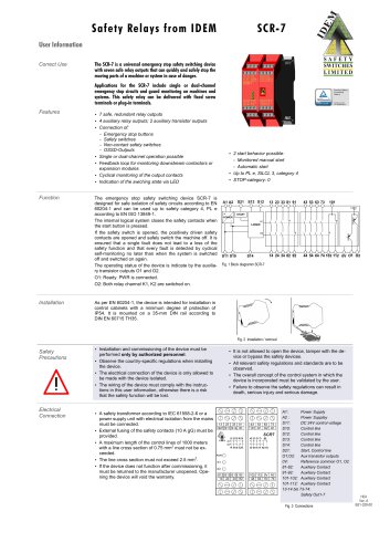 SCR-7
SCR-74 Pages
 Python Line Series
8 Pages
 MICRO SWITCHES
4 Pages
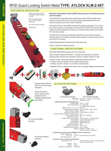 KLM-Z-4ST
2 Pages
 GLS-SS
1 Page
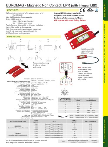 LPR (with Integral LED)
1 Page
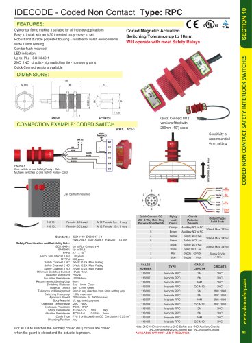 RPC
RPC1 Page
 INCH-3
1 Page
 RAMZLOCK KLTM-RFID
4 Pages
 IDEM 2012 PRODUCT CATALOGUE
152 Pages









Archived catalogs
 2008 Main Catalogue
56 Pages
- Single-pole switch
- Push-button switch
- Technology switch
- Multipole switch
- Electromechanical switch
- Rotary electric switch
- Limit switch
- IP67 switch
- Metal switch
- Plastic switch
- Hermetic switch
- AC electric switch
- Metal push-button switch
- Industrial switch
- Emergency stop push-button switch
- DC switch
- Heavy-duty switch
- Safety relay
- Stainless steel switch