


XA series

XA series
- Available in two button sizes: ø29mm and ø40mm.
- Lead-free and RoHS compliant.
- Standard depth behind the panel is 27.9mm for 1 to 4 contacts, and 23.9mm for unibody models with 1NC or 2NC contacts.
- Features IDEC's "Safe break action" ensuring NC contacts open when detached.
- Push-to-lock, pull or turn-to-reset operation.
- Direct opening action mechanism and safety lock mechanism compliant with IEC standards.
- Protection degree: IP65 for standard and IP65/IP40 for unibody models.
- UL, c-UL recognized, and EN compliant.
- Applicable standards include IEC60947-5-1, EN60947-5-1, UL508, and others.
- Operating temperature ranges from -25 to +60°C for non-illuminated and -25 to +55°C for illuminated models.
- Operating humidity is 45 to 85% RH.
- Mechanical life is a minimum of 250,000 operations, and electrical life is 100,000 operations minimum.
- Contact resistance is 50mΩ maximum, and insulation resistance is 100MΩ minimum.
- Standard rated insulation voltage is 300V (60V for illuminated parts).
- Rated current is 5A, with specific ratings for resistive and inductive loads at different voltages.
- Instructions for removing and installing contact blocks and LED units are provided, emphasizing the need for careful handling to avoid damage.
- Wiring instructions specify using 16 AWG maximum wire size and proper soldering techniques.
- Safety precautions include turning off power before installation and using appropriate tools to avoid injury.
Catalog excerpts

Switches & Pilot Devices ø16mm XA E-Stops Switches & Pilot Devices Signaling Lights Relays & Sockets • Two button sizes: ø29 and ø40mm • Lead-free, RoHS compliant, (EU directive 2002/95/EC) • Depth behind the panel: Standard - only 27.9mm for 1 to 4 contacts Unibody - only 23.9mm for 1NC or 2NC • IDEC’s original “Safe break action” ensures that the NC contacts open when the contact block is detached from the operator. • Push-to-lock, Pull or Turn-to-reset operator • Direct opening action mechanism (IEC60947-5-5, 5.2, IEC60947-5-1, Annex K) • Safety lock mechanism (IEC60947-5-5, 6.2) • Degree of protection: Standard - IP65 (IEC60529) Unibody - IP65 and IP40 (IEC 60529) • UL, c-UL recognized. EN compliant • UL NISD2 category emergency stop button (File# E305148) Specifications Model Applicable Standards Operating Temperature Non‑illuminated: –25 to +60°C (no freezing), Illuminated: –25 to +55°C (no freezing) Operating Humidity Storage Temperature Operating Force Push‑to‑lock: 10.5N Pull‑to‑reset: 10N Turn‑to‑reset: 0.16N·m Minimum Force Required for Direct Opening Action Min Operator Stroke Required for Direct Opening Action Maximum Operator Stroke Contact Resistance Gold plated silver Insulation Resistance Impulse Withstand Voltage Pollution Degree Operation Frequency Shock Resistance Operating extremes: 150 m/s2, Damage limits: 1000 m/s2 Terminal Blocks Operating extremes: 10 to 500Hz, amplitude 0.35mm acceleration 50m/s2, Damage limits: 10 to 500Hz, amplitude 0.35mm acceleration 50m/s2 Mechanical Life Electrical Life 100,000 operations minimum, (250,000 operations minimum @ 24V AC/DC, 100mA) Degree of Protection Terminal Style 50mΩ maximum (initial value) Contact Material Vibration Resistance Solder terminal, PC board terminal Recommended Tightening Torque for Locking Ring Wire Size Soldering Conditions Note: Except for stop switches (operator color: yellow and gray)
Open the catalog to page 1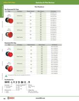
Switches & Pilot Devices Switches & Pilot Devices Part Numbers Non-Illuminated XA E-Stop Style Monitor Contacts Main Contacts Part Number Signaling Lights – Relays & Sockets Solder Terminal Illuminated XA E-Stop Style Main Contacts Part Number Solder Terminal Solder Terminal Terminal Blocks All illuminated XA E-Stops come with a replaceable 24V AC/DC LED. Circuit Breakers XA1E - L V 3 11 Q4 V - R Illumination B: Non-Illuminated L: Illuminated Mushroom Size 3: ø29mm 4: ø40mm Terminal Blank: solder tab V: PCB Voltage Code Blank: Non-illuminated Q4: Illuminated 24V AC/DC
Open the catalog to page 2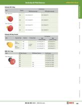
Switches & Pilot Devices ø16mm XA E-Stops Switches & Pilot Devices Unibody XA E-Stop Style Part Number Signaling Lights Unibody XA Stop Switch Relays & Sockets Part Number Style Operator Type EMO XA E-Stop Part Number XA1E-BV402-RH-EMO Terminal Blocks Circuit Breakers
Open the catalog to page 3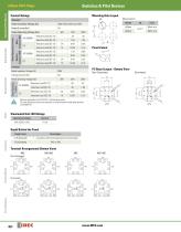
Switches & Pilot Devices Contact Ratings Mounting Hole Layout Rated Insulation Voltage (Ui) Depth Behind the Panel Description 1 - 4 contacts, both illuminated and non-illuminated Terminal Arrangements (Bottom View) Circuit Breakers Illuminated Unit LED Ratings 24V AC/DC ±10% Minimum applicable load: 5V AC/DC, 1mA (reference value). The rated operating currents are measured at resistive/inductive load types specified in IEC 60947-5-1. Operating Voltage Rated Operating Current Relays & Sockets Rated Operating Voltage (Ue) PC Board Layout - Bottom View Panel Cutout Resistive Load (AC-12) Inductive...
Open the catalog to page 4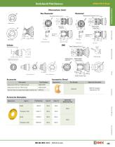
Switches & Pilot Devices ø16mm XA E-Stops Switches & Pilot Devices Illuminated Mounting Panel Thickness: 0.5 to 3.7 Mounting Panel Thickness: 0.5 to 3.7 Rubber Gasket Locking Ring Rubber Gasket Solder Terminal Type Solder Terminal Relays & Sockets PC Board Terminal Type Signaling Lights Locking Ring Panel Cut-out Mounting Hole Solder/Tab Terminal #110 (Behind the panel: 23.9) Rubber Gasket Locking Ring Solder Terminal Type Accessories: Shroud Description Applicable Standards SEMI S2 Compliant (Approved by TUV) Terminal Cover for contact block (solder terminal only) Replacement LED Unit: PCB Terminal...
Open the catalog to page 5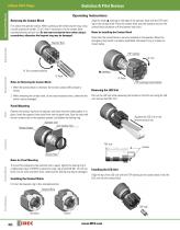
Switches & Pilot Devices Switches & Pilot Devices Operating Instructions Removing the Contact Block First unlock the operator button. While pushing up the white bayonet ring, using a small screwdriver (width: 2.5 to 3 mm) if necessary, turn the contact block counterclockwise and pull out. Do not exert excessive force when using a screwdriver, otherwise the bayonet ring may be damaged. Notes for Installing the Contact Block Check that the contact block is securely installed on the operator. When the emergency stop switch is properly assembled, the bayonet ring is in place as shown below. Signaling...
Open the catalog to page 6
Switches & Pilot Devices ø16mm XA E-Stops Switches & Pilot Devices Operating Instructions, continued Wiring Installing Insulation Terminal Cover 1. The applicable wire size is 16 AWG maximum. To install the terminal cover (XA9Z-VL2), align the TOP marking on the terminal cover with TOP marking on the contact block, and press the terminal cover toward the contact block. 2. Solder the terminal at a temperature of 310 to 350°C within 3 seconds using a soldering iron. Sn-Ag-Cu solder is recommended. When soldering, do not touch the switch with the soldering iron. Also ensure that no tensile force...
Open the catalog to page 7All IDEC catalogs and technical brochures
 MACHINE TOOLS Industry Solutions
28 Pages
 ROBOTICS Industry Solutions
27 Pages
 Relay Selection Guide
16 Pages
 PUSH-IN PRODUCTS
12 Pages
 PRODUCT GUIDE
44 Pages
 HR6S
HR6S32 Pages
 KW2D SERIES
16 Pages
 LED-Leuchten: LF2B
6 Pages
 LED Illumination Units
28 Pages
 LED-Leuchten: LF1B-N
4 Pages
 Katalog FL1E
16 Pages
 RS485-Kommunikationsmodul
2 Pages
 Automation Organizer
2 Pages
 Web-Server-Modul
4 Pages
 MicroSmart DC12V
4 Pages
 FT1A SmartAXIS
36 Pages
 RTE/GT3/GE1A/GT5P/GT5Y
68 Pages
 Universalrelais RR/RY/RH/RU
59 Pages
 RJ.S Relays und Sockets
12 Pages
 RV8H-Baureihe
6 Pages
 E-Stop Switches
16 Pages
 High Performance
4 Pages
 HG1X
HG1X3 Pages
 FL1E
FL1E4 Pages
 product brochure
6 Pages
 All Product Brochure
6 Pages
 Complete Contactors Catalog
60 Pages
 Complete Terminal Blocks Catalog
22 Pages
 Complete Timer Catalog
68 Pages
 Complete Relay & Socket Catalog
68 Pages
 Complete Display Lights Catalog
44 Pages
 Complete Safety Overview
6 Pages
 Complete Power Supply Catalog
22 Pages
 Complete O/I Catalog
22 Pages
 Complete PLC Catalog
68 Pages



- Power supply unit
- DC power supply
- AC/DC power supply
- Rectangular housing
- Ethernet switch
- Electric gearmotor
- Industrial network switch
- LED lighting
- Plastic housing
- Single-pole switch
- Windows software
- Cloud-based software
- Push-button switch
- Waterproof network switch
- Power supply for industrial applications
- Switched-mode power supply
- Unmanaged switch
- Photoelectric sensor
- Compact power supply
- Indoor enclosure