Universalrelais RR/RY/RH/RU
1 /59Pages

Universalrelais RR/RY/RH/RU
1 /59Pages
Catalog excerpts

Relays Sockets RU/RR/RH/RM/RY & Latch Relays General-purpose electromechanical relays Relay sockets for mounting in three ways
Open the catalog to page 1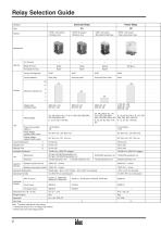
Relay Selection Guide Universal Relay Power Relay Type • DPDT, 10A contact • Miniature size • 4PDT, 6A contact • Miniature size • 4PDT, 3A contact • Bifurcated contact type • SPDT, 10A contact • Heavy duty power relay Blade Terminal Contact Configuration Silver alloy Contact Material Gold-clad silver-nickel Rated Load (resistive load) Rated Voltage Power Consumption (approx.) Pickup Voltage (against rated values) Dropout Voltage (against rated values) Contact Resistance Operate Time Release Time Insulation Resistance Dielectric Strength AC type: 50,000,000 operations min. DC type: 100,000,000...
Open the catalog to page 2
Relay Selection Guide Power Relay Power Relay • DPDT, 3PDT; 10A contact • Heavy duty power relay • SPDT, DPDT, 3PDT, 4PDT; 10A contact • Miniature size Silver cadmium oxide 10A Pin terminal: Blade terminal:
Open the catalog to page 3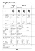
Relay Selection Guide Miniature Relay Miniature Relay • DPDT, 5A contact • Miniature lightweight relay • DPDT, 4PDT; 3A or 5A contact • 1A bifurcated contact also available Blade Terminal PC Board Terminal Contact Configuration Contact Material DPDT (bifurcated) Gold-clad silver Silver palladium Rated Load (resistive load) Rated Voltage Power Consumption (approx.) Pickup Voltage (against rated values) Dropout Voltage (against rated values) Operate Time Release Time Contact Resistance Between contact and coil Between same-pole contacts Insulation Resistance Dielectric Strength Operating Temperature...
Open the catalog to page 4
Relay Selection Guide Latch Relay RR2KP RH2L • DPDT; 10A contact • Midget power latch relay • With a mechanical operation indicator • DPDT; 10A contact • Dual coil latch relay RY2KS • DPDT; 3A contact • Dual coil latch relay Silver cadmium oxide Gold-plated silver Set coil: 1.2 VA (60Hz), 2W Reset coil: 0.5 VA (60Hz), 0.9W
Open the catalog to page 5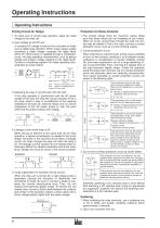
Operating Instructions Operating Instructions Driving Circuit for Relays Protection for Relay Contacts 1. To make sure of correct relay operation, apply the rated voltage to the relay coil. 1. The contact ratings show the maximum values. Make sure that these values are not exceeded at any instant. When an inrush current ows through the load, the contact may be welded. If this is the case, connect a contact protection circuit, such as a current limiting resistor. 2. Input voltage for the DC coil: A complete DC voltage is best for the coil power to make sure of stable relay operation. When using...
Open the catalog to page 6
Operating Instructions Other Precautions 1. General notice: • To maintain the initial characteristics, do not drop the relay or apply shocks to the relay. • The relay housing cannot be removed from the base during normal operation. To maintain the initial characteristics, do not remove the relay housing. • Use the relay in environments free from condensation of dust, sulfur dioxide (SO2), and hydrogen sulde (H2S). • Make sure that the coil voltage does not exceed the applicable coil voltage range. 2. When connecting outputs to electronic circuits: When the output is connected to a load which...
Open the catalog to page 7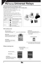
RU Series Universal Relays Full featured universal miniature relays Designed with environment taken into consideration • Two terminal styles: plug-in and PCB mount • Non-polarized LED indicator available on plug-in relays • No internal wires, lead-free construction • Cadmium-free contacts • Mechanical flag indicator available on plug-in relays • Manual latching lever with color coding for AC or DC coil • Snap-on yellow marking plate; optional marking plates are available in four other colors • Maximum contact ratings: 10A (RU2), 6A (RU4), 3A (RU42) • UL, CSA, c-UL, EN compliant Standard UL508...
Open the catalog to page 8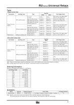
RU Series Universal Relays Types • Single Contact Type Termination Latching Lever Coil Voltage Code ∗ Plug-in Terminal (Note 1) Without Latching Lever Without Latching Lever With RC (AC coil only) With diode (DC coil only) With diode (DC coil only) Reverse polarity coil With Latching Lever With RC (AC coil only) With diode (DC coil only) With diode (DC coil only) Reverse polarity coil Simple (Note 2) Simple (Note 2) • Bifurcated Contact Type Termination Latching Lever Coil Voltage Code ∗ Plug-in Terminal (Note 1) Without Latching Lever Without Latching Lever With RC (AC coil only) With diode...
Open the catalog to page 9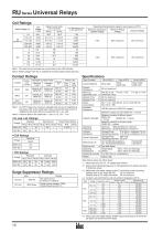
RU Series Universal Relays Coil Ratings Rated Current (mA) ±15% (at 20°C) Coil Voltage Code Dropout Voltage Minimum Pickup Voltage Operating Characteristics (against rated values at 20°C) Maximum Continuous Applied Voltage Note 1: The rated current includes the current draw by the LED indicator. Note 2: Rated voltage 100V DC is available for the bifurcated contact type only. Contact Ratings Contact Continu- Allowable Contact Power ous Resistive Inductive Current Load Load 2500VA AC 1250VA AC 300W DC 150W DC Rated Load Ind. Load Contact Resistance Minimum Applicable Load Operate Time Release Time...
Open the catalog to page 10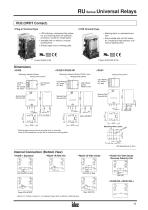
RU Series Universal Relays RU2 (DPDT Contact) • Plug-in Terminal Type • PCB Terminal Type • LED indicator, mechanical flag indicator, and marking plate are standard provisions, except on simple types. • Available with or without a manual latching lever • Simple types have a marking plate. • Marking plate is a standard provision. • Not provided with an LED indicator, mechanical ag indicator, and manual latching lever. Color Marking AC: Yellow DC: Blue Color Marking AC: Yellow DC: Blue LED Indicator (green) (RU2S-C only) Marking Plate Removal Slot Marking Plate Removal Slot Marking Plate Removal...
Open the catalog to page 11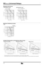
RU Series Universal Relays Electrical Life Curves • RU2 (Resistive Load) Maximum Switching Current • RU2 AC resistive AC inductive (cos ø = 0.3) Ambient Temperature vs. Temperature Rise Curves • RU2 (AC Coil, 50 Hz) Load current 10A × 2 poles Load current 5A × 2 poles Load current 10A × 2 poles Load current 5A × 2 poles Load current 10A × 2 poles Load current 5A × 2 poles The above temperature rise curves show the characteristics when 100% the rated coil voltage is applied. The heat resistance of the coil is 120°C. The slant dashed line indicates the allowable temperature rise for the coil at...
Open the catalog to page 12All IDEC catalogs and technical brochures
 MACHINE TOOLS Industry Solutions
28 Pages
 ROBOTICS Industry Solutions
27 Pages
 Relay Selection Guide
16 Pages
 PUSH-IN PRODUCTS
12 Pages
 PRODUCT GUIDE
44 Pages
 HR6S
HR6S32 Pages
 KW2D SERIES
16 Pages
 LED-Leuchten: LF2B
6 Pages
 LED Illumination Units
28 Pages
 LED-Leuchten: LF1B-N
4 Pages
 Katalog FL1E
16 Pages
 RS485-Kommunikationsmodul
2 Pages
 Automation Organizer
2 Pages
 Web-Server-Modul
4 Pages
 MicroSmart DC12V
4 Pages
 FT1A SmartAXIS
36 Pages
 RTE/GT3/GE1A/GT5P/GT5Y
68 Pages
 RJ.S Relays und Sockets
12 Pages
 RV8H-Baureihe
6 Pages
 E-Stop Switches
16 Pages
 XA series
7 Pages
 High Performance
4 Pages
 HG1X
HG1X3 Pages
 FL1E
FL1E4 Pages
 product brochure
6 Pages
 All Product Brochure
6 Pages
 Complete Contactors Catalog
60 Pages
 Complete Terminal Blocks Catalog
22 Pages
 Complete Timer Catalog
68 Pages
 Complete Relay & Socket Catalog
68 Pages
 Complete Display Lights Catalog
44 Pages
 Complete Safety Overview
6 Pages
 Complete Power Supply Catalog
22 Pages
 Complete O/I Catalog
22 Pages
 Complete PLC Catalog
68 Pages


- SARRALLE power supply
- SARRALLE DC power supply
- SARRALLE AC/DC power supply
- Rectangular housing
- Ethernet switch
- Electric gearmotor
- Industrial network switch
- LED lighting
- Plastic housing
- Single-pole switch
- SARRALLE Windows software
- SARRALLE cloud software
- Push-button switch
- Switching power supply
- SARRALLE power supply for industrial applications
- Waterproof network switch
- Unmanaged switch
- Compact power supply
- Indoor enclosure
- SARRALLE simulation software