RTE/GT3/GE1A/GT5P/GT5Y
1 /68Pages

RTE/GT3/GE1A/GT5P/GT5Y
1 /68Pages
Catalog excerpts
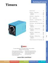
Switching & Controls Switches & Pilot Lights Display Lights Relays & Sockets General Instructions for All Timer Series .. 858 Terminal Blocks For more information on this product family, visit our website. Additional resources include: • Downloadable manuals & CAD drawings • Manufacturer’s suggested retail price list • Product training schedule & locations • Advertising & trade show schedules • Press releases & FAQs Circuit Breakers • New and updated product information • Downloadable software demos & upgrades • Part conguration tool & cross reference • Online stock check & ordering • IDEC eld sales & distributor search • Online literature request www.idec.com/timer Table of Contents
Open the catalog to page 1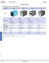
Selection Guide Switches & Pilot Lights Selection Guide Selection Guide: RTE, GT3A, GT3D, and GT3F Series Series Model ON-delay Interval OFF-delay One-shot Cycle (ON rst) Cycle (OFF rst) Signal OFF delay Signal ON/OFF delay ON-delay Interval OFF-delay One-shot Cycle (off rst) Cycle (on rst) Signal OFF delay Signal ON/OFF delay ON-delay Interval One-shot One-shot ON delay Cycle Signal OFF delay Signal ON/OFF delay True OFF-delay Time Range Contact Conguration SPDT, DPDT SPDT, DPDT SPDT, DPDT Repeat Accuracy Contact Load Rating (resistive) Available Operating Voltage Relays & Sockets Display Lights...
Open the catalog to page 2
Selection Guide Selection Guide Switches & Pilot Lights Selection Guide: RTE, GT3A, GT3D, and GT3F Series Series Model Time Range Star side: 0.05s to 100s Star-delta Switching Time: 0.05, 0.1, 0.25, 0.5 seconds Contact Conguration SPDT, DPDT Repeat Accuracy Available Operating Voltage Display Lights Sequential start ON-delay Recycler and instantaneous Recycler OFF start Recycler ON start Interval Interval ON delay Sequential interval Relays & Sockets Contact Load Rating (resistive) 1. For Timing Diagrams Overview, see page 794.. 2. For all series specic instructions, accessories, and dimensions,...
Open the catalog to page 3
Timing Diagrams Overview Switches & Pilot Lights Timing Diagrams Overview Guide to Reading Timing Function Diagrams Power Applied Start Input Start Input Terminals Shorted Terminals Opened Power Removed Timer Power 1. If power is disconnected during actual timing, most electronic timers reset to the preset time, ready for the re-application of supply voltage (except for GT3F “true OFF Delay”). 2. NO = Normally open. 3. NC = Normally closed. Input Signal NC Contact Opens Display Lights Timer Begins Counting Timing Function Diagrams Overview Relays & Sockets ON-Delay 1 (power start) ON-Delay 2...
Open the catalog to page 4
Timing Diagrams Overview Cycle 2 (signal start, OFF rst) When voltage is applied to the coil, the contacts remain in the off state and the set time begins. At the end of the set time, the contacts transfer to the on state and remain in the on state until the set time elapses. The timer cycles between the two states until power is removed from the coil. Removing the coil voltage resets the timer. The set time for both the on state and the off state is the same. Applicable models: GT3A-1, -2, -3, GT3D-1, -2, -3, -4 and RTE-P(B)1. Voltage is applied to the coil at all times. When a start signal...
Open the catalog to page 5
Timing Diagrams Overview Switches & Pilot Lights Voltage is supplied to the coil at all times. When a maintained start signal is supplied, the contacts immediately transfer to the on state and the set time begins. When the set time has elapsed, the contacts transfer to the off state. The contacts remain in the off state until the start signal is removed. The contacts transfer back to the on state and remain in the on state for the set time. When the set time has elapsed, the contacts transfer to the off state and remain in the off state until the start signal is supplied again (no reset is necessary)....
Open the catalog to page 6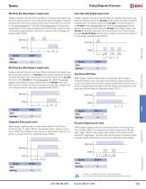
Timing Diagrams Overview Cycle One-Shot Output (signal start) Voltage is applied to the coil at all times. When a momentary start signal is supplied, the contacts remain in the off state and the preset time begins. Following the preset time, the contacts transfer to the on state and remain in the on state for the one-shot preset time. Following the one-shot preset time, the contacts transfer back to the off state and remain there until the timer is reset. The timer can be reset by applying either a reset input or removal of the coil voltage. Applicable model: GT3D-8. Voltage is applied to the...
Open the catalog to page 7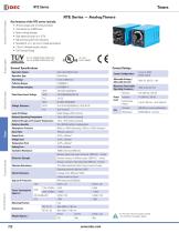
Display Lights Switches & Pilot Lights RTE Series — Analog Timers Key features of the RTE series include: • • • • • • • • 20 time ranges and 10 timing functions Time delays up to 600 hours Space-saving package High repeat accuracy of ± 0.2% ON and timing OUT LED indicators Standard 8- or 11-pin and 11-blade termination 2 form C delayed output contacts 10A Contact Rating Cert. No. E9950913332316 (EMC, RTE) Cert. No. BL960813332355 (LVD, RTE) General Specications Contact Ratings Solid state CMOS Circuit Operation Type Time Range Pollution Degree Over voltage category Relays & Sockets Operation...
Open the catalog to page 8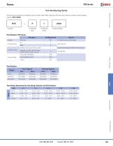
RTE Series Part Numbering Guide Switches & Pilot Lights RTE series part numbers are composed of 4 part number codes. When ordering a RTE series part, select one code from each category. Example: RTE-P1AF20 Part Numbers: RTE Series j Series Part Number Code For internal circuits, see next page. ON-delay, interval, cycle OFF, cycle ON Each function group has different timing functions. ON-delay, cycle OFF, cycle ON, signal ON/OFF delay, OFF-delay, one-shot Relays & Sockets Display Lights Part Numbers Voltage Start Input Triggered Time Range Determined by Time Range Selector and Dial Selector Dial...
Open the catalog to page 9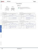
Switches & Pilot Lights 1. RTE-B1: Do not apply voltage to terminals #2, #5 & #8. 2. IDEC sockets are as follows: RTE-P1: SR2P-06* pin type socket, RTE-B1: SR3B-05* blade type socket, (*-may be followed by sufx letter A,B,C or U). Display Lights A: ON-Delay 1 (power start) Set timer for desired delay, apply power to coil. Contacts transfer after preset time has elapsed, and remain in transferred position until timer is reset. Reset occurs with removal of power. Item Power Delayed Contact Terminal Number B: Interval (power start) Set timer for desired delay, apply power to coil. Contacts transfer...
Open the catalog to page 10All IDEC catalogs and technical brochures
 MACHINE TOOLS Industry Solutions
28 Pages
 ROBOTICS Industry Solutions
27 Pages
 Relay Selection Guide
16 Pages
 PUSH-IN PRODUCTS
12 Pages
 PRODUCT GUIDE
44 Pages
 HR6S
HR6S32 Pages
 KW2D SERIES
16 Pages
 LED-Leuchten: LF2B
6 Pages
 LED Illumination Units
28 Pages
 LED-Leuchten: LF1B-N
4 Pages
 Katalog FL1E
16 Pages
 RS485-Kommunikationsmodul
2 Pages
 Automation Organizer
2 Pages
 Web-Server-Modul
4 Pages
 MicroSmart DC12V
4 Pages
 FT1A SmartAXIS
36 Pages
 Universalrelais RR/RY/RH/RU
59 Pages
 RJ.S Relays und Sockets
12 Pages
 RV8H-Baureihe
6 Pages
 E-Stop Switches
16 Pages
 XA series
7 Pages
 High Performance
4 Pages
 HG1X
HG1X3 Pages
 FL1E
FL1E4 Pages
 product brochure
6 Pages
 All Product Brochure
6 Pages
 Complete Contactors Catalog
60 Pages
 Complete Terminal Blocks Catalog
22 Pages
 Complete Timer Catalog
68 Pages
 Complete Relay & Socket Catalog
68 Pages
 Complete Display Lights Catalog
44 Pages
 Complete Safety Overview
6 Pages
 Complete Power Supply Catalog
22 Pages
 Complete O/I Catalog
22 Pages
 Complete PLC Catalog
68 Pages


- SARRALLE power supply
- SARRALLE DC power supply
- SARRALLE AC/DC power supply
- Rectangular housing
- Ethernet switch
- Electric gearmotor
- Industrial network switch
- LED lighting
- Plastic housing
- Single-pole switch
- SARRALLE Windows software
- SARRALLE cloud software
- Push-button switch
- Switching power supply
- SARRALLE power supply for industrial applications
- Waterproof network switch
- Unmanaged switch
- Compact power supply
- Indoor enclosure
- SARRALLE simulation software