RJ.S Relays und Sockets
1 /12Pages

RJ.S Relays und Sockets
1 /12Pages
Catalog excerpts

Think Automation and beyond... RJ/SJ RJ Series Slim Power Relays SJ Series Relay Sockets
Open the catalog to page 1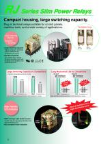
RJ Series Slim Power Relays Compact housing, large switching capacity. Plug-in terminal relays suitable for control panels, machine tools, and a wide variety of applications. Large Switching Capacity Excellent Durability • Large Switching Capacity Highly conductive materials ensure stable electric conduction of current. • Excellent Durability Our unique return spring structure provides improved durability and reliability of all mechanical parts. Large Switching Capacity vs. Competitors Long Mechanical Life vs. Competitors AC Coil (maximum allowable switching current) operations minimum 50 million...
Open the catalog to page 2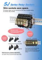
SJ Series Relay Sockets Slim sockets save space. RJ series relays can be mounted on DIN rails or panels using SJ series relay sockets. 15.5 mm Release Lever Relays can be easily removed using release levers. Easy Wiring! • Standard Screw Terminal Type Similar Dimensions • Finger-safe Screw Terminal Type (IP20) RoHS directive compliant (2002/95/EC) By combining with the RU series relays, the contact capacity increases and more contact conguration types become available. Because the screw terminal size is M3 on both sockets, wiring can be completed easily and efciently. The RJ series relays and...
Open the catalog to page 3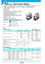
RJ Series Slim Power Relays Compact and rugged power relays. Large switching capacity. • Compact housing only 12.7-mm wide. Large contact rating RJ1S (1-pole): 12A RJ2S (2-pole): 8A • Non-polarized LED indicator available. IDEC’s unique light guide structure enables high visibility of coil status from any direction. • Excellent electrical and mechanical life. Electrical life: 200,000 operations (AC load) Mechanical life: 30 million operations (AC coil) • Environmentally friendly, RoHS directive compliant (EU directive 2002/95/EC). Contains no lead, cadmium, mercury, hexavalent chromium, PBB or...
Open the catalog to page 4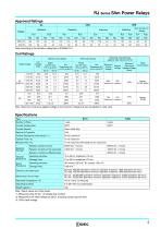
RJ Series Slim Power Relays Approved Ratings UL Note: According to the utilization categories of IEC60947-5-1 Coil Ratings Without LED Indicator Rated Voltage Coil Voltage Code Coil Minimum Resistance (Ω) Pickup ±10% (at 20°C) Voltage Power Maximum Consumption Dropout Continuous Voltage Applied Voltage (Note) Operating Characteristics (against rated values at 20°C) Note: Maximum continuous applied voltage is the maximum voltage that can be applied on relay coils. Specifications Type Contact Conguration Contact Material Silver-nickel alloy Contact Resistance (initial value) (∗1) 10 ms maximum...
Open the catalog to page 5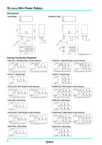
RJ Series Slim Power Relays Dimensions • RJ2S-CL Type Internal Connection Diagrams ∗ • RJ1S-CL-∗ Standard Type (w/LED Indicator) 1 (A1) ∗ • RJ2S-CL-∗ Standard Type (w/LED Indicator) 1 (A1) Coil voltage 24V AC/DC and below Coil voltage greater than 24V AC/DC Coil voltage 24V AC/DC and below Coil voltage greater than 24V AC/DC ∗ • RJ1S-CLD-∗ With Diode (w/LED Indicator) 1 (A1) – ∗ • RJ2S-CLD-∗ With Diode (w/LED Indicator) 1 (A1) – Coil voltage 24V DC and below Coil voltage greater than 24V DC Coil voltage 24V DC and below Coil voltage greater than 24V DC ∗ • RJ1S-CLD1-∗ With Diode (w/LED Indicator)...
Open the catalog to page 6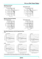
RJ Series Slim Power Relays Electrical Life Curve • RJ1 (resistive load) 250V AC Resistive Load (NO contact) 30V DC Resistive Load (NO Contact) 250V AC Resistive Load (NO contact) 30V DC Resistive Load (NO Contact) Maximum Switching Capacity • RJ1 (resistive load) Operating Temperature and Coil Temperature Rise Load Current 12A × 1 pole Load Current 12A × 1 pole Load Current 12A × 1 pole Load Current 8A × 2 poles Load Current 8A × 2 poles Load Current 8A × 2 poles The above temperature rise curves show characteristics when 100% the rated coil voltage is applied. The slanted dashed line indicates...
Open the catalog to page 7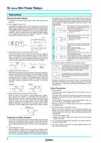
RJ Series Slim Power Relays Instructions 1. To make sure of correct relay operation, apply rated voltage to the relay coil. 2. Input voltage for the DC coil: A complete DC voltage is best for the coil power to make sure of stable relay operation. When using a power supply containing a ripple voltage, suppress the ripple factor within 5%. When power is supplied through a rectication circuit, the relay operating characteristics, such as pickup voltage and dropout voltage, depend on the ripple factor. Connect a smoothing capacitor for better operating characteristics as shown below. the release...
Open the catalog to page 8
SJ Series Relay Sockets Slim, space-saving relay sockets. Release lever allows for easy maintenance in narrow spaces. • 15.5-mm wide • Standard screw terminal and nger-safe screw terminal are available. • Degree of protection IP20 (nger-safe screw terminal) • The release lever makes installation and removal of relays inside small panels simple and quick. • RoHS compliant (EU directive 2002/95/EC) • UL recognized, CSA certied, EN compliant. Standard Approval organization / File No. EC Low Voltage Directive (Finger-safe screw terminal only) Type Standard Screw Terminal Finger-safe Screw Terminal...
Open the catalog to page 9
RJ Series Relay Sockets Dimensions • SJ1S-05B Replacement Parts Description Package Quantity Plastic (gray) Release Lever Accessories Description Aluminum Weight: Approx. 200 g Steel Weight: Approx. 200 g Package Quantity Mounting Clip Used on a DIN rail to fasten relay sockets. To prevent the sockets from damage, position the clip before fastening. Metal (zinc plated steel) Weight: Approx.15 g Plastic (black) Thickness: 5 mm Used for adjusting spacing between sockets mounted on a DIN rail
Open the catalog to page 10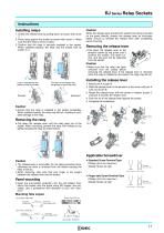
RJ Series Relay Sockets Instructions Installing relays 1. Unlock the release lever by pulling down as shown with arrow ➀. 2. Press relay against the socket as shown with arrow ➁. Make sure that the relay is rmly in place. 3. Conrm that the relay is securely installed in the socket. When installed properly, the relay and the socket look as shown in ➂. When the release lever prevents the socket from being mounted on the panel directly, remove the release lever as instructed below. Ensure to reinstall the release lever after completing panel mounting. Removing the release lever • Pull down the release...
Open the catalog to page 11All IDEC catalogs and technical brochures
 MACHINE TOOLS Industry Solutions
28 Pages
 ROBOTICS Industry Solutions
27 Pages
 Relay Selection Guide
16 Pages
 PUSH-IN PRODUCTS
12 Pages
 PRODUCT GUIDE
44 Pages
 HR6S
HR6S32 Pages
 KW2D SERIES
16 Pages
 LED-Leuchten: LF2B
6 Pages
 LED Illumination Units
28 Pages
 LED-Leuchten: LF1B-N
4 Pages
 Katalog FL1E
16 Pages
 RS485-Kommunikationsmodul
2 Pages
 Automation Organizer
2 Pages
 Web-Server-Modul
4 Pages
 MicroSmart DC12V
4 Pages
 FT1A SmartAXIS
36 Pages
 RTE/GT3/GE1A/GT5P/GT5Y
68 Pages
 Universalrelais RR/RY/RH/RU
59 Pages
 RV8H-Baureihe
6 Pages
 E-Stop Switches
16 Pages
 XA series
7 Pages
 High Performance
4 Pages
 HG1X
HG1X3 Pages
 FL1E
FL1E4 Pages
 product brochure
6 Pages
 All Product Brochure
6 Pages
 Complete Contactors Catalog
60 Pages
 Complete Terminal Blocks Catalog
22 Pages
 Complete Timer Catalog
68 Pages
 Complete Relay & Socket Catalog
68 Pages
 Complete Display Lights Catalog
44 Pages
 Complete Safety Overview
6 Pages
 Complete Power Supply Catalog
22 Pages
 Complete O/I Catalog
22 Pages
 Complete PLC Catalog
68 Pages


- SARRALLE DC power supply
- SARRALLE AC/DC power supply
- Rectangular housing
- Ethernet switch
- Electric gearmotor
- Industrial network switch
- LED lighting
- Plastic housing
- Single-pole switch
- SARRALLE Windows software
- SARRALLE cloud software
- Push-button switch
- Switching power supply
- SARRALLE power supply for industrial applications
- Waterproof network switch
- Unmanaged switch
- Compact power supply
- Indoor enclosure
- SARRALLE simulation software