


Complete Enabling Switches Catalog

Complete Enabling Switches Catalog
This document provides comprehensive information on enabling switches, focusing on their specifications, applications, and safety features. These switches are crucial for ensuring operator safety during machine operation, especially in hazardous environments.
- Definition: A 3-position switch (OFF-ON-OFF) that allows machine operation only when lightly pressed and held in the middle position, ensuring safety by disabling operation when released or further depressed.
- Applications: Commonly used in teach pendants for robots to protect operators from unpredictable motions.
- Key Features: 3-position functionality, positive action contacts, lightweight, and reliable.
- Specifications: Conforms to international standards, operates within -25 to +60°C, and has a mechanical life of at least 1,000,000 operations.
- Protection: IP40 excluding terminal part, with recommended short circuit protection.
- Key Features: Offers redundant contacts for enhanced reliability, available with or without a rubber cover for IP65 protection.
- Specifications: Similar to HE1B but includes additional monitoring contacts and higher mechanical life.
- Key Features: Snap acting contacts, available with or without rubber cover, ensuring high safety standards.
- Specifications: Conforms to similar standards as HE1B and HE2B, with a focus on pushbutton operation.
The document includes part numbers, installation instructions, and detailed specifications for each switch type, ensuring users can select the appropriate switch for their needs.
- HE3B, HE5B, and HE1G Models: Designed for safety applications, particularly in environments requiring manual robotic control.
- Specifications: Conform to standards such as IEC60947-5-1, EN60947-5-1, and UL508, with specific temperature and humidity ranges and defined mechanical and electrical life spans.
- HE5B Series: Offers IP65 protection with a waterproof rubber cover and mounts in a 16mm round hole.
The switches feature a 3-position OFF-ON-OFF operation, with specific force requirements for each position. The HE5B series requires a light force to maintain position 2, facilitating ease of use. The operating force and stroke vary depending on whether the rubber cover is used.
Proper installation is crucial to maintain the waterproof performance of the switches. The document advises against penetrating the rubber cover and provides guidelines for mounting panel thickness and soldering. Recommended wire sizes and torque specifications are also provided to ensure safe and effective installation.
The document emphasizes the importance of following installation specifications to prevent electric shock or fire. It also highlights the need for periodic checks to ensure the switches are functioning correctly, especially when the rubber boot is used. The switches should be connected to a monitoring device for maximum reliability.
Replacement parts such as rubber covers and lock nut tools are available, with specific part numbers and materials listed for each accessory.
The HE1G series is noted for its ergonomic design and high safety level, meeting ANSI RIA 15.06 robotics standards. It includes optional features like an E-Stop switch and momentary pushbutton, with IP66 waterproof sealing.
Catalog excerpts

OverviewX Series E-StopsDoor Interlock Switches 419 > Enabling Switches BarriersAs-Interface Safety at Work New and updated product information Օ Downloadable software demos & upgrades Part confi guration tool & cross reference Օ Online stock check & ordering IDEC fi eld sales & distributor search Օ Online literature request Downloadable manuals & CAD drawings Օ Manufacturers suggested retail price list ҕ Product training schedule & locations Advertising & trade show schedules Օ Press releases & FAQs Table of Contents Automation & Sensing - Pg. 1Safety - Pg. 315Switching & Controls - Pg. 439Index - Pg. 911 size="-1">
Open the catalog to page 1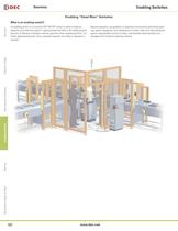
Enabling Dead ManӔ Switches What is an enabling switch? An enabling switch is a 3-position (OFF-ON-OFF) switch to allow a machine operation only when the switch is lightly pressed and held in the middle position (position 2). Because it disables machine operation when released (position 1) or further depressed (position 3) by a panicked operator, the safety of operators is ensured.Because operators use pendants in hazardous environments performing teach-ing, system changeover, and maintenance of robots, they must have protection against unpredictable motion of robots, and therefore teach pendants...
Open the catalog to page 2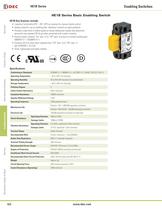
OverviewX Series E-StopsDoor Interlock Switches Enabling SwitchesBarriresAS-Interface Safety at Work Conforming to Standards IEC60947-5-1, EN60947-5-1, JIS C8201-5-1, UL508, CSA C22.2 No 14 Operating Temperature 25 to +60C (no freezing) Operating Humidity 45 to 85% RH maximum (no condensation) Storage Temperature ږ40 to +80˚C (no freezing) Pollution Degree 2 Initial Contact Resistance 50m maximum Insulation Resistance 100M minimum Impulse Withstand Voltage 2.5kV Operating Frequency 1200 operations/hour Position 1 2: 1,000,000 operations minimumPosition 1 Mechanical Life 2 3 1: 100,000 operations...
Open the catalog to page 4
ItemInstallationPart Number > OverviewX Series E-StopsDoor Interlock SwitchesEnabling SwitchesBarriersAS-Interface Safety at Work Side HE1B-M1FrontHE1B-M1N > Rated Insulation Voltage (Ui) AC / DC250V Thermal Current (lth) 5A Rated Operating Voltage (Ue) 30V125V250V 3A1.5A Rated OperatingCurrent (le)AC 50/60HzResistive Load (AC-12) Inductive Load (AC-15) ֖1.5A0.75A 2A0.4A0.2A DCResistive Load (DC-12) Inductive Load (DC-13) 1A0.22A0.1A Contact Structure SPST-NO three position (OFF-ON-OFF) > Minimum applicable load: AC/DC3V 5mA (For reference only). Position 1Position 2Position 3 > Approx. 15NApprox....
Open the catalog to page 5
When pressed toposition 3: 2 13.6 24 430 > 7 OverviewX Series E-StopsDoor Interlock Switches Enabling SwitchesBarriresAS-Interface Safety at Work 5 413 482.8 7.612 Solder Terminal > M3 15 min. 24 > 0.5 9 min. Screw Length = (panel thickness + 5 to 6mm)Panel Thickness1mm - 2mm 24 > ѱ0.2 Insert the nuts supplied with the switch. When using a panel thicker than 2mm, the button will be lower than the surface of the panel >
Open the catalog to page 6
OverviewX Series E-StopsDoor Interlock SwitchesEnabling SwitchesBarriersAS-Interface Safety at Work Application Standards ISO12100/EN292, IEC60204-1/EN60204-1, ISO11161/prEN11161, ISO10218/EN775, ANSI/RIA R15.06 Operating Temperature Ԗ25 to +60˚C (no freezing) Operating Humidity 45 to 85% RH (no condensation) Storage Temperature 40 to +80C (no freezing) 2 (inside of panel/contact side)3 (outside of panel/operating side) Pollution Degree Contact Resistance 50m maximum Between live and dead metal parts: 100M maximumBetween positive and negative live parts: 100M minimum > Insulation Resistance...
Open the catalog to page 7
Position 1Position 2Position 3 > OverviewX Series E-StopsDoor Interlock SwitchesEnabling SwitchesBarriersAS-Interface Safety at Work Approx. 30NApprox. 4N > Operating Force (reference value) (without rubber boot, when pressingthe center of the operator) Travel (mm) 1.4 > 0.3 2.4 > ѱ 0.3 3.0 > 0.3 3.6 > ѱ 0.5 4.2 > 0.5 6.0 > ѱ 0.5 Between NO1 - C1When pressing the operatorBetween NO2 - C2Between 11 - 12Between 21 - 22Between 31 - 32Between 41 - 42Between NO1 - C1When releasing the operatorBetween NO2 - C2Between 11 - 12Between 21 - 22Between 31 - 32Between 41 - 42 : ON (closed): OFF (open) > Using...
Open the catalog to page 9
OverviewX Series E-StopsDoor Interlock Switches Enabling SwitchesBarriresAS-Interface Safety at Work Conforming to Standards IEC60947-5-1, EN60947-5-1, JIS C8201-5-1, UL508, CSA C22.2 No 14 Application Standards ISO12100/EN292, IEC60204-1/EN60204-1, ISO11161/prEN11161, ISO10218/EN775, ANSI/RIA R15.06 Operating Temperature 25 to +60C (no freezing) Operating Humidity 45 to 85% RH maximum (no condensation) Storage Temperature ږ40 to +80˚C (no freezing) Pollution Degree 3 Contact Resistance 50m maximum Between live & dead metal parts: 100M maximumBetween positive & negative live parts: 100M minimum...
Open the catalog to page 10
OverviewX Series E-StopsDoor Interlock Switches Enabling SwitchesBarriresAS-Interface Safety at Work
Open the catalog to page 12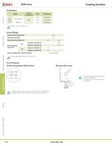
ModelContact ArrangementColorPart Number With Rubber CoverSilicone RubberDPDTYellow HE5B-M2PYBlackHE5B-M2PBNBR/PVCGrayHE5B-M2PN1 > OverviewX Series E-StopsDoor Interlock Switches Enabling SwitchesBarriresAS-Interface Safety at Work NBR/PVC cover comes in gray only. Rated Insulation Voltage (Ui) 125V Thermal Current (lth) 3A Rated Operating Voltage (Ue) 30V125V 0.5A Rated OperatingCurrent (le)ACResistive Load (AC-12) Inductive Load (AC-15) ֖0.3A 1A DCResistive Load (DC-12) Inductive Load (DC-13) 0.7A֖ Contact Confi guration (3 Position Switch) 2 contacts (DPDT) > Minimum applicable load (reference):...
Open the catalog to page 14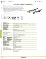
OverviewX Series E-StopsDoor Interlock Switches Enabling SwitchesBarriresAS-Interface Safety at Work GS-ET-15 BG standard in Germany Direct OpeningAction DoubleInstallation Conforming to Standards IEC60947-5-1, EN60947-5-1, JIS C8201-5-1, UL508, CSA C22.2 No 14 Applicable Standards ISO12100/EN292, IEC60204-1/EN60204-1, ISO11161/prEN11161, ISO10218/EN775, ANSI/RIA R15.06, Operating Temperature Ԗ25 to +60˚C (no freezing) Operating Humidity 45 to 85% RH maximum (no condensation) Storage Temperature 40 to +80C (no freezing) Pollution Degree 3 Contact Resistance 100m maximum Insulation Resistance...
Open the catalog to page 16All IDEC catalogs and technical brochures
 MACHINE TOOLS Industry Solutions
28 Pages
 ROBOTICS Industry Solutions
27 Pages
 Relay Selection Guide
16 Pages
 PUSH-IN PRODUCTS
12 Pages
 PRODUCT GUIDE
44 Pages
 HR6S
HR6S32 Pages
 KW2D SERIES
16 Pages
 LED-Leuchten: LF2B
6 Pages
 LED Illumination Units
28 Pages
 LED-Leuchten: LF1B-N
4 Pages
 Katalog FL1E
16 Pages
 RS485-Kommunikationsmodul
2 Pages
 Automation Organizer
2 Pages
 Web-Server-Modul
4 Pages
 MicroSmart DC12V
4 Pages
 FT1A SmartAXIS
36 Pages
 RTE/GT3/GE1A/GT5P/GT5Y
68 Pages
 Universalrelais RR/RY/RH/RU
59 Pages
 RJ.S Relays und Sockets
12 Pages
 RV8H-Baureihe
6 Pages
 E-Stop Switches
16 Pages
 XA series
7 Pages
 High Performance
4 Pages
 HG1X
HG1X3 Pages
 FL1E
FL1E4 Pages
 product brochure
6 Pages
 All Product Brochure
6 Pages
 Complete Contactors Catalog
60 Pages
 Complete Terminal Blocks Catalog
22 Pages
 Complete Timer Catalog
68 Pages
 Complete Relay & Socket Catalog
68 Pages
 Complete Display Lights Catalog
44 Pages
 Complete Safety Overview
6 Pages
 Complete Power Supply Catalog
22 Pages
 Complete O/I Catalog
22 Pages
 Complete PLC Catalog
68 Pages



- Power supply unit
- DC power supply
- AC/DC power supply
- Rectangular housing
- Ethernet switch
- Electric gearmotor
- LED lighting
- Industrial network switch
- Plastic housing
- Single-pole switch
- Windows software
- Cloud-based software
- Push-button switch
- Power supply for industrial applications
- Switched-mode power supply
- Waterproof network switch
- Unmanaged switch
- Photoelectric sensor
- Compact power supply
- Indoor enclosure