Complete Door Interlock Switches Catalog

Complete Door Interlock Switches Catalog
Catalog excerpts

Interlock Switches Selection Guide XW Series E-Stops Overview Selection Guide Standard Interlock Safety Switches Series Subminiature HS5D HS2B HS1B 271 www.IDEC.com/safety 276 283 287 30 x 15 x 78mm 91 x 30 x 30mm 30 x 30 x 90mm 52 x 35 x 98mm 52 x 35 x 125mm Appearance Page Size (mm) Termination Interlock Switches Full Size HS5B Contacts Enabling Switches Miniature HS6B Material 2 or 3 2 2 or 3 2 2 Integrated cable Screw Screw Screw Screw Plastic body Plastic body Metal or plastic head Plastic head Die-cast aluminum body Solenoid Locking Safety Switches Series Subminiature Miniature HS6E Full...
Open the catalog to page 2
Standard Interlock Safety Switches HS6B HS6B Subminiature Interlock Switches Overview Key features: • Only 78 x 30 x 15mm • Two actuator entrances provide flexibility for installation options • Integrated molded cable reduces wiring time • IP67 (IEC60529) • Direct Opening Action • Actuators comply with ISO14119 and EN1088 XW Series E-Stops Direct Opening Action GS-ET-15 BG standard in Germany Double Insulation Interlock Switches Part Numbers Actuator Keys (order separately) Part Number 1NC-1NO 1m HS6B-11B01 3m HS6B-11B03 5m HS6B-11B05 1m HS6B-02B01 3m HS6B-02B03 5m HS6B-02B05 1m HS6B-12B01 3m...
Open the catalog to page 3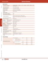
Interlock Switches Selection Guide Specifications Operating Temperature –25 to +70˚C (no freezing) Storage Temperature –40 to +80˚C (no freezing) 45 to 85% RH (no condensation) Storage Humidity 95% maximum (no condensation) Altitude Overview EN1088, IEC60947-5-1, EN60947-5-1, GS-ET-15, IEC60664-1, IEC60204-1, EN60204-1, UL508, CSA C22.2 No. 14 Relative Humidity XW Series E-Stops Conforming to Standards 2,000m maximum Pollution Degree 3 Rated Insulation Voltage (Ui) 300V Impulse Withstand Voltage (Uimp) Insulation Resistance 4kv Between live & dead metal parts: 100MΩ maximum Between positive &...
Open the catalog to page 4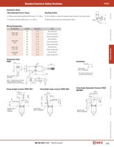
Standard Interlock Safety Switches HS6B Installation Notes Handling Cables • Do not tighten or loosen the fastened cable conduit of the safety switch • Actuator installation (M4 screw): 1.0~1.5N-m • Minimum bend radius of installed cable: 40mm Gland um nim ius Mi ad R mm 40 (100) • Safety switch body installation (M4 screw): 1.0~1.5N-m Overview Recommended Screw Torque Wiring Designations Contact blue-blue/white 21-22 brown-brown/white NO 33-34 orange-orange/white NC 11-12 blue-blue/white NC 21-22 brown-brown/white NC HS6B-03B01 (3NC) Color 11-12 NC HS6B-12B01 (2NC-1NO) Terminal # NC 31-32 orange-orange/white...
Open the catalog to page 5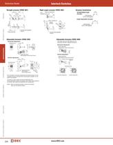
2-ø9 28.2 7.5 5.5 25 34 20° 8.4 3.5 1.2 Horizontal Adjustment The base is made of glass-reinforced PA66 (66 nylon). Angle adjustment screws are stainless steel. When using adhesive on screws, take material compatibility into consideration. Vertical Adjustment 20° • Actuator Mounting Hole Layout Straight/Right-angle Actuator 20° 3.5 1.2 13.1 14 34 4.3 3.5 10.4 1.2 metal key inserted in opposite directions. (M3 Hexagon Socket Head Screw) 2-ø 8.4 20° 16.8 20° 5.5 25 25 34 34 Enabling Switches R2 2.5 Angle Adjustment (M3 Hexagon 4 H .1 Socket Head Screw) ole s) (M Orienting Insert Orienting Insert...
Open the catalog to page 6
Standard Interlock Safety Switches HS6B Minimum Radius of Hinged Door Note: Because deviation or dislocation of hinged door may occur in actual applications, make sure of the correct operation before installation. HS9Z-A62 Actuator M 1 im 60 m um m Ra di us M in 1 im 60 m um m Ra di us 50 mm Radius Minimum m 50 m dius Door Hinge Minimum Ra Door Hinge Label Label HS9Z-A65 HS9Z-A65 HS9Z-A66 HS9Z-A66 in Door Hinge Door Hinge 2 im 30 m um m Ra di us Door Hinge Label Label HS9Z-A65 HS9Z-A65 HS9Z-A66 HS9Z-A66 Door Hinge 50 mm Door Hinge Minimum Radiu 50 mm s Minimum Radiu s • When the door hinge is...
Open the catalog to page 7
Interlock Switches Selection Guide Key features: • Detects detachment of head for enhanced safety • Compact dimensions with up to three contacts • The head orientation can be rotated, allowing 8 different actuator entries • NC contacts with direct opening action (IEC/EN60947-5-1) • M3 terminal screws for easy wiring • Gold-plated contacts suitable for small loads XW Series E-Stops Overview HS5D Miniature Interlock Switches Part Numbers Actuator Keys (order separately) Interlock Switches Contact Configuration 1NC-1NO Plastic Head Type Metal Head Type 11 Monitor Circuit Zb 23 2NC Main Circuit 11...
Open the catalog to page 8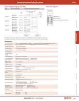
Standard Interlock Safety Switches Contact Configuration & Operation Chart Contact Conguration Contact Configuration Terminal Arrangement Contact Operation Chart (reference) Contact Operation Chart (reference) 0 (Actuator Mounting Reference Position) 0 (Actuator Mounting Reference Position) Approx. Approx. 4.6 6.7 Approx. Approx. 4.6 6.7 HS5D-11* HS5D-11* HS5D-12* HS5D-12* HS5D-03* HS5D-03* 11 11 12 12 23 23 24 24 11 11 12 12 21 21 22 22 11 11 21 21 33 33 11 11 21 21 12 12 22 22 34 34 12 12 22 22 11-12 11-12 23-24 23-24 11-12 11-12 Approx. 26.4 (Travel: mm) Approx. 26.4 (Travel: mm) : Contact...
Open the catalog to page 9
Interlock Switches Selection Guide Overview Contact Ratings Operating Voltage (Ue) 125V 250V – 2.5A 1.5A Inductive load (AC-15) – 1.5A 0.75A Resistive load (DC-12) 2.5A 1.1A 0.55A (1A) AC Rated Operating Current (Ie) 30V (0.22A) (0.1A) Resistive load (AC-12) DC Recommended Screw Torque • Safety switch body installation (M4 screw): 1.0~1.5N-m • Actuator installation (M4 screw): 1.0~1.5N-m Gland um nim ius Mi ad R mm 40 (100) XW Series E-Stops Installation Notes 1 Gland Port 91 HS5D-ZRN (Metal Head) With HS9Z-A51 Straight Actuator + RP: Reference mounting position. Plastic (red) Plastic (gray)...
Open the catalog to page 10
15 15 24 24 30 30 15 15 24 24 30 30 2-M4 Screws 7.6 ±1 7.6 Slot Plug (supplied) Slot Plug (supplied) (Note) (Note) Standard Interlock Safety Switches Hole Layout Mounting Mounting Hole Layout HS6B 15 15 24 24 30 30 6±1 6±1 20 to 22 20 to 22 2-M4 Screws 2-M4 Screws Actuator Actuator Actuator Stop Actuator Stop 36.2 36.2 91 91 6 ±1 6 ±1 11 20 20 30 30 11 Gland Port Gland Port 15 15 24 24 30 30 91 91 20 20 28 28 11 20 20 30 30 36.2 36.2 11 28 28 20 20 36 36 5.2 5.2 XW Series E-Stops Actuator Actuator Actuator Stop Actuator Stop Slot Plug (supplied) Slot Plug (supplied) (Note) (Note) Gland Port Gland...
Open the catalog to page 11All IDEC catalogs and technical brochures
 Web Server Module
2 Pages
 IDEC FL1D SmartRelay
12 Pages
 MicroSmart
28 Pages
 AP22M Series
4 Pages
 IDEC E-S top Switches
6 Pages
 Complete Contactors Catalog
60 Pages
 Circuit Breakers Catalog
12 Pages
 Complete Terminal Blocks Catalog
22 Pages
 Complete Timer Catalog
52 Pages
 Complete Relay & Socket Catalog
76 Pages
 Complete Display Lights Catalog
44 Pages
 Complete Safety Overview
4 Pages
 Sensor catalog
55 Pages
 Complete Power Supply Catalog
20 Pages
 Complete O/I Catalog
29 Pages
 Complete PLC Catalog
64 Pages
 All Product Brochure
6 Pages


- Display module
- LCD display panel
- LED lighting
- Single-pole switch
- Windows software
- IO module
- Junction block
- Level probe
- Push-button switch
- Liquid level sensor
- Switching relay
- Analog I/O
- Technology switch
- Multipole switch
- Photoelectric sensor
- Programmable logic controller
- Programming software
- Touch screen HMI
- Electromechanical switch
- Electromechanical relay