Complete Door Interlock Switches Catalog

Complete Door Interlock Switches Catalog
This document provides comprehensive information on safety and automation products, specifically focusing on door interlock switches. It includes specifications, installation instructions, safety precautions, and recommendations for various series of interlock switches.
The document details specifications for several series of door interlock switches, including HS6B, HS5B, HS2B, and others. Key specifications include size and dimensions, body material options, solenoid and LED indicator availability, conformance to standards like EN1088 and IEC60947-5-1, operating conditions, and electrical characteristics.
Installation instructions are provided, covering recommended screw torque, handling and wiring guidelines, and actuator installation and adjustment.
Safety precautions are highlighted to prevent electric shock, fire, and mechanical damage, such as ensuring power is off before installation, using safety relays, and avoiding PLCs in circuits between the switch and load.
Recommendations for optimal use include using proprietary actuators, covering unused actuator entry slots, and ensuring proper actuator entry direction during installation.
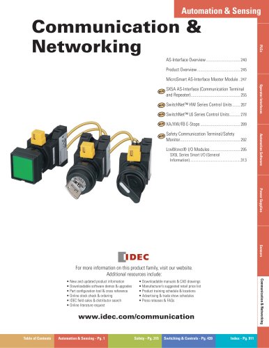
The document mentions additional resources available online, such as product information, software demos, part configuration tools, and downloadable manuals.
The HS5B Series Door Interlock Switches are designed for safety applications, ensuring machinery cannot operate when doors are open. They conform to standards such as EN1088 and IEC60947-5-1, operate within a temperature range of -20 to +70°C, and have a degree of protection rated at IP67.
The HS2B series features compact and lightweight plastic housing, direct opening action, and flexible installation options. It offers IP67 protection and conforms to international standards.
The HS1B series features a rugged aluminum die-cast housing and offers similar safety and installation flexibility as the HS2B series.
The HS6E series is noted for its compact size and energy-saving design, including a solenoid lock mechanism and manual unlocking options.
Detailed installation instructions are provided, including the use of gaskets and sealing tape to ensure IP67 protection, along with circuit diagrams and application examples.
The document serves as a comprehensive guide for selecting and installing door interlock switches, emphasizing safety, flexibility, and compliance with international standards.
Catalog excerpts
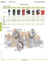
Series ModelHS6BHS5BHS2BHS1BHS6EHS5EHS1EHS1CAppearance > OverviewX Series E-StopsDoor Interlock SwitchesEnabling SwitchesBarriersAS-Interface Safety at Work Page 345350357361365376384392 Size(mm) 78 x 15 x 30mm91 x 30 x 30mm98 x 57 x 40mm125 x 64 x 40mm75 x 15 x 75mm146 x 35 x 40mm104mm x 39.7mm x 129mm125 x 106 x 39.7mm Body Material Plastic HousingPlastic Housing (metallic actuator entry optional)Plastic HousingDie-cast alumi-numPlastic HousingPlastic Housing/Metallic Actuator EntryPlastic HousingDie-cast alumi-num Solenoid (Yes/No) NoNoNoNoYesYesYesYes LED Indicator NoNoYesYesYesYesYesYes...
Open the catalog to page 2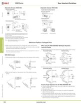
Orienting Insert Angle Adjustment(M3 Hexagon Socket Head Screw) 0.8 1.23.5 Angle Adjustment(M3 Hexagon Socket Head Screw) 20 OverviewX Series E-StopsDoor Interlock SwitchesEnabling SwitchesBarriersAS-Interface Safety at Work 20а Actuator Stop (supplied)(Note 2)Angle Adjustment(M3 Hexagon Socket Head Screw) 7.5 28.2 13 2.5 2 20 5.5 20а 16.8 25 34 Orienting InsertHorizontal AdjustmentVertical Adjustment R2.1 15 Angle Adjustment(M3 Hexagon Socket Head Screw)Orienting Insert (M4 Holes) 50 mm 50 mm Minimum Radius Minimum Radius Door Hinge Door Hinge Label Label > HS9Z-A65HS9Z-A66 HS9Z-A66HS9Z-A65...
Open the catalog to page 6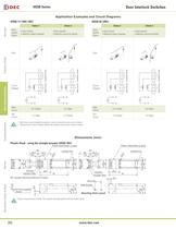
OverviewX Series E-StopsDoor Interlock SwitchesEnabling SwitchesBarriersAS-Interface Safety at Work Main CircuitAuxiliary Circuit Main CircuitAuxiliary Circuit Main CircuitAuxiliary Circuit Main CircuitAuxiliary Circuit + + + + - - - - > 1. Main Circuit: used to enable the machine to start only when the main circuit is closed.2. Auxiliary Circuit: used to indicate whether the machine circuit or door is open or closed. > 15 15 Plug the unused actuator insertion slot using the slot plug supplied with the interlock switch. >
Open the catalog to page 10
Plastic Head (black or gray) Plastic Head (black or gray) > OverviewX Series E-StopsDoor Interlock SwitchesEnabling SwitchesBarriersAS-Interface Safety at Work 27.7 41.5 35.3 27.7 > R2.2 R2.2 1 1 20 30 20 30 20 20 30 30 1 1 Actuator CoverActuatorActuator StopActuator Stop Conduit PortConduit PortRPRP 36.2 36.2 91 Actuator CoverActuator 91 7.6 ֱ 1 20 to 22 > 1 2-M4 Screws > 7.6 Slot Plug (supplied) (Note) > 30 30 24 24 15 15 Note: Plug the unused actuator entry slot using the slot plug supplied with the interlock switch. > 15 Note: Plug the unused actuator insertion slot using the slot plug supplied...
Open the catalog to page 11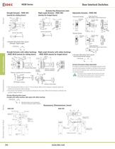
OverviewX Series E-StopsDoor Interlock SwitchesEnabling SwitchesBarriersAS-Interface Safety at Work 30 28 15 20 49 >
Open the catalog to page 12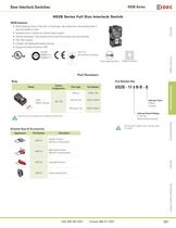
OverviewX Series E-StopsDoor Interlock SwitchesEnabling SwitchesBarriersAS-Interface Safety at Work EN1088EN60947-5-1 IEC60947-5-1 GS-ET-15 BG standard in Germany Direct Opening Action Double Insulation > ModelContact Confi gurationPilot LightPart Number > HS2B(plastic housing)1NC-1NOWithout HS2B-11NBWith red LEDHS2B-114NB-RWith green LEDHS2B-114NB-G Indicator Color R (Red), G (Green) Indicator Rated Voltage 4 (24V DC) Blank (without indicator) > Order the actuators separately (not supplied with the switch). Not necessary to specify color if indicator option not chosen. AppearancePart NumberDescription...
Open the catalog to page 15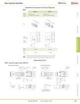
OverviewX Series E-StopsDoor Interlock SwitchesEnabling SwitchesBarriersAS-Interface Safety at Work > Main CircuitAuxiliary Circuit Main CircuitAuxiliary Circuit >
Open the catalog to page 17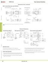
OverviewX Series E-StopsDoor Interlock SwitchesEnabling SwitchesBarriersAS-Interface Safety at Work >
Open the catalog to page 18
OverviewX Series E-StopsDoor Interlock SwitchesEnabling SwitchesBarriersAS-Interface Safety at Work EN1088EN60947-5-1 IEC60947-5-1 GS-ET-15 BG standard in Germany Direct Opening Action > ModelContact Confi gurationPilot LightPart Number > HS1B (alum. die-cast housing) 1NC-1NOWithout HS1B-11RWith red LEDHS1B-114R-RWith green LEDHS1B-114R-G2NCWithout HS1B-02RWith red LEDHS1B-024R-RWith green LEDHS1B-024R-G Indicator Color R (Red), G (Green) Housing Color R (Red) Indicator Rated Voltage > 1. The special key wrench (HS9Z-T1) for removing the cover and manual unlocking is included with the switch.2....
Open the catalog to page 19
OverviewX Series E-StopsDoor Interlock SwitchesEnabling SwitchesBarriersAS-Interface Safety at Work Main CircuitAuxiliary Circuit Main CircuitAuxiliary Circuit + + - - > Main CircuitAuxiliary Circuit Main CircuitAuxiliary Circuit + + - - > 1. Main Circuit: used to enable the machine to start only when the main circuit is closed. Auxiliary Circuit: used to indicate whether the main circuit or door is open or closed.2. Terminals + and - are used for the LED indicator, and are isolated from door status. Wire the terminals only when needed. >
Open the catalog to page 21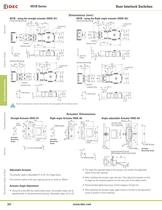
OverviewX Series E-StopsDoor Interlock SwitchesEnabling SwitchesBarriersAS-Interface Safety at Work 42 52 6415 4.5 42 52 6415 4.5 224043 >
Open the catalog to page 22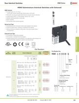
OverviewX Series E-StopsDoor Interlock SwitchesEnabling SwitchesBarriersAS-Interface Safety at Work Direct OpeningAction DoubleInstallation Lock MechanismCircuit NumberContact Confi gurationCable LengthPart Number > (Standard Stock in bold) > (Actuator inserted) (Solenoid OFF) Spring Lock L Main Circuit: 1NC + 1NC, Monitor Circuit: 2NC/1NO G (Green) > A1A2(+)() A1A2(+)(֖) Cable Length Indicator Color Housing Color 01: 1m 03: 3m 05: 5m B (Black) 1m > Main Circuit: 414212112122 3m HS6E-L44B03-G 5m HS6E-L44B01-G HS6E-L44B05-GMMain Circuit: 1NC + 1NC, Monitor Circuit: 2NC/1NC Indicator Rated Voltage...
Open the catalog to page 23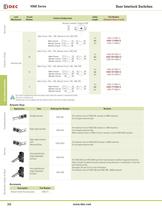
Lock MechanismCircuit NumberContact Confi gurationCable LengthPart Number (Standard Stock in bold) (Actuator inserted) (Solenoid ON) Solenoid Lock L Main Circuit: 1NC + 1NC, Monitor Circuit: 2NC/1NO > A1A2(+)() A1A2(+)(֖) OverviewX Series E-StopsDoor Interlock SwitchesEnabling SwitchesBarriersAS-Interface Safety at Work 1m > Main Circuit: 414212112122 3m HS6E-L7Y4B03-G 5m HS6E-L7Y4B01-G HS6E-L7Y4B05-GMMain Circuit: 1NC + 1NC, Monitor Circuit: 2NC/1NC > Monitor Circuit:Monitor Circuit: 31325354 1m > Main Circuit: 414212112122 3m HS6E-M7Y4B03-G > Monitor Circuit:Monitor Circuit: 31325152 5m HS6E-M7Y4B01-G...
Open the catalog to page 24
Operating Temperature UL 508 (UL listed), CSA C22.2, No. 14 (c-UL listed), ISO 14119IEC 60947-5-1, EN 60947-5-1 (TV approval), EN 1088 (TܜV approval), GS-ET-19 IEC 60204-1/EN 60204-1 (applicable standards for use) 25 to +50ְC (no freezing) Conforming to Standards Storage Temperature 40 to +80ְC (no freezing) > OverviewX Series E-StopsDoor Interlock SwitchesEnabling SwitchesBarriersAS-Interface Safety at Work Operating Humidity 45 to 85% (no condensation) Rated Insulation Voltage (Ui) 300V (between LED and ground: 60V) Main & lock monitor circuits: 1.5 KVDoor monitor circuit: 2.5 kV Between solenoid/LED...
Open the catalog to page 25All IDEC catalogs and technical brochures
 MACHINE TOOLS Industry Solutions
28 Pages
 ROBOTICS Industry Solutions
27 Pages
 Relay Selection Guide
16 Pages
 PUSH-IN PRODUCTS
12 Pages
 PRODUCT GUIDE
44 Pages
 HR6S
HR6S32 Pages
 KW2D SERIES
16 Pages
 LED-Leuchten: LF2B
6 Pages
 LED Illumination Units
28 Pages
 LED-Leuchten: LF1B-N
4 Pages
 Katalog FL1E
16 Pages
 RS485-Kommunikationsmodul
2 Pages
 Automation Organizer
2 Pages
 Web-Server-Modul
4 Pages
 MicroSmart DC12V
4 Pages
 FT1A SmartAXIS
36 Pages
 RTE/GT3/GE1A/GT5P/GT5Y
68 Pages
 Universalrelais RR/RY/RH/RU
59 Pages
 RJ.S Relays und Sockets
12 Pages
 RV8H-Baureihe
6 Pages
 E-Stop Switches
16 Pages
 XA series
7 Pages
 High Performance
4 Pages
 HG1X
HG1X3 Pages
 FL1E
FL1E4 Pages
 product brochure
6 Pages
 All Product Brochure
6 Pages
 Complete Contactors Catalog
60 Pages
 Complete Terminal Blocks Catalog
22 Pages
 Complete Timer Catalog
68 Pages
 Complete Relay & Socket Catalog
68 Pages
 Complete Display Lights Catalog
44 Pages
 Complete Safety Overview
6 Pages
 Complete Power Supply Catalog
22 Pages
 Complete O/I Catalog
22 Pages
 Complete PLC Catalog
68 Pages


- SARRALLE power supply
- SARRALLE DC power supply
- SARRALLE AC/DC power supply
- Rectangular housing
- Ethernet switch
- Electric gearmotor
- Industrial network switch
- LED lighting
- Plastic housing
- Single-pole switch
- SARRALLE Windows software
- SARRALLE cloud software
- Push-button switch
- Switching power supply
- SARRALLE power supply for industrial applications
- Waterproof network switch
- Unmanaged switch
- Compact power supply
- Indoor enclosure
- SARRALLE simulation software