

- Products
- Catalogs
- News & Trends
- Exhibitions
Complete AS-Interface Safety at Work

Complete AS-Interface Safety at Work
AS-Interface Safety at Work integrates a safety network into a single wire-saving system. It allows for the connection of safety slaves and monitors to an existing AS-Interface network, facilitating the integration of interlock switches, safety relay modules, and emergency stop switches. This system reduces wiring and allows for connection to other networks through gateways.
The XA, XW, and FB Series emergency stop switches are designed for direct connection to the AS-Interface Safety at Work network. They comply with IEC 61508 SIL3 and EN954-1 safety category 4 standards, offering space, wire, and labor-saving solutions. These switches are available in various sizes and configurations, including illuminated and non-illuminated options, with different terminal connectors for effective connection.
Operating voltage ranges from 26.5 to 31.6V DC, with different current ratings for illuminated and non-illuminated types. The devices are designed to operate within specific temperature and humidity ranges and offer protection against corrosion and vibration. The communication protocol is AS-Interface Ver. 3.0, supporting a maximum network length of 100 meters and up to 31 safety slaves.
The switches require specific operating forces for push-lock and pull/turn reset actions. They have a mechanical and electrical life of at least 250,000 operations. Various connector types are available, and specific torque values are recommended for installation.
Instructions cover wiring and installation, including static electricity discharge, torque specifications, and panel mounting guidelines. The document also details the process for replacing safety slaves and monitors, setting addresses, and ensuring proper network configuration. It emphasizes the importance of using appropriate cables and avoiding excessive force during operation.
Catalog excerpts

AS-Interface Safety at Work Overview Overview AS-Interface Safety at Work AS-Interface safety at work integrates a safety network into one wire-saving system. • Emergency stop switches can be connected directly to AS-Interface Safety at Work, further reducing wiring. • Interlock switches, safety relay modules and other safety components can be connected to the safety network via safety slaves. • Safety components can be connected to other networks through gateways. XW Series E-Stops • Safety slaves and safety monitors can be simply connected to the existing AS-Interface network to establish the...
Open the catalog to page 2
AS-Interface Safety at Work Overview Overview MicroSmart Series AS-Interface Master Module + FC4A FC5A Interlock Switches Non-contact Interlock Switch XW Series E-Stops PLC Gateway SX5A AS-Interface Safety / Gateway Enabling Switches SX5A AS-Interface I/O Module Safety Control Control Unit SX5A AS-Interface Safety Monitor PS2R AS-Interface Power Supplies Light Curtains Safety slaves and standard slaves can be connected to one network. 800-262-IDEC (4332) • USA & Canada HW Series AS-Interface Safety at Work Photoelectric Switches L6 Series 443
Open the catalog to page 3
AS-Interface Safety at Work Emergency Stop Switches Overview Emergency Stop Switches XA Series/XW Series/FB Series (Plastic Enclosures) with Safety Slave Functions for Direct Connection to the AS-Interface Safety at Work Interlock Switches XW Series E-Stops • Emergency stop switches with safety slave functions can be connected to the AS-Interface Safety at Work network. • Complies with IEC 61508 SIL3 (Functional safety of electrical/electronic/programmable electronic safety-related systems) and EN954-1 safety category 4 (Safety of machinery-Safety related parts of control systems). • Space, wire,...
Open the catalog to page 4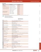
AS-Interface Safety at Work Emergency Stop Switches Accessories Part Number XA/XW Series IDC Connector Kit 1 XW9Z-C100-1 Through connector (with cover) XW9Z-C100-2 IDC Connector Termination Tool Manufactured by ITW Pancon MMIT-156F Length 500 mm, with one connector XW9Z-C205 Length 1m, with one connector XW9Z-C210 Length 300 mm, straight FB9Z-CS03 Length 1m, straight FB9Z-CS10 Length 2m, straight FB9Z-CS20 Length 1m, right-angle FB9Z-CL10 Length 2m, right-angle FB9Z-CL20 2 SX9Z-ADR1N Crimping Type Connector Cable FB Series Control Station M12 Connector Cable Hand-held Programming Device XW Series...
Open the catalog to page 5
AS-Interface Safety at Work Emergency Stop Switches Minimum Operator Stroke Required for Direct Opening Action 4.0 mm Maximum Operating Stroke 4.5 mm Operating Frequency 900 operations/hour Mechanical Life 250,000 operations minimum Electrical Life 250,000 operations minimum Connectors Mechanical/Electrical XW Series E-Stops 60N (XA series), 80N (XW, FB series) IDC connector (XA series) IDC connector, crimping connector (XW series) M12 connector/AS-Interface piercing connector (FB series) Recommended Tightening Torque for Locking Ring Interlock Switches Pushlock: 10.5N (XA series), 32N (XW, FB...
Open the catalog to page 6
AS-Interface Safety at Work Emergency Stop Switches Dimensions XW Series ø40 29.6 IDC Connector (Optional) 45 50.3 30.3 ø4 0 1.7 +0.2 0 R0 .8 ø2 ma 2.3 ø60 x. Panel Cut-out 20.6 FB Series 3.2 +0.2 0 +0 .4 0 17.9 +0.2 0 6.2 IDC Connector (Optional) XW Series E-Stops ø1 54.2 59.5 32 +0.2 0 20.1 24.1 +0.4 0 20.6 33.6 ø2 9 Communication Block 17.4 Communication Block 31.1 Overview XA Series Panel Cut-out 32 M12 Connector Cable for FB Series L 4-M4 Tapping Screw Holes for Rear Mounting (Depth: 10 mm) 2-Front Mounting Holes ø14 Knockout 5 25 35 Interlock Switches 20 40 7 × 4.2 19 21 41 76.0 21 AS-Interface...
Open the catalog to page 7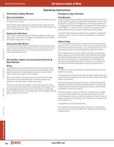
Operating Instructions AS-Interface Safety at Work XW Series E-Stops Overview Operating Instructions AS-Interface Safety Monitor Emergency Stop Switches Wiring and Installation Panel Mounting Before wiring the interface cable, discharge static electricity. Tighten the screws to a torque of 0.8 to 1.2 N·m. The AS-Interface power supply unit must separate the main power (input) and output safely according to IEC 60742. It must also maintain a stable supply in the event of instantaneous power failure. Replacing the Safety Slave Press “Service” button before and after replacing the safety slave....
Open the catalog to page 8All IDEC catalogs and technical brochures
 Web Server Module
2 Pages
 IDEC FL1D SmartRelay
12 Pages
 MicroSmart
28 Pages
 AP22M Series
4 Pages
 IDEC E-S top Switches
6 Pages
 Complete Contactors Catalog
60 Pages
 Circuit Breakers Catalog
12 Pages
 Complete Terminal Blocks Catalog
22 Pages
 Complete Timer Catalog
52 Pages
 Complete Relay & Socket Catalog
76 Pages
 Complete Display Lights Catalog
44 Pages
 Complete Safety Overview
4 Pages
 Sensor catalog
55 Pages
 Complete Power Supply Catalog
20 Pages
 Complete O/I Catalog
29 Pages
 Complete PLC Catalog
64 Pages
 All Product Brochure
6 Pages


- Display module
- LCD display panel
- LED lighting
- Single-pole switch
- Windows software
- Junction block
- Push-button switch
- Level probe
- Liquid level sensor
- Switching relay
- Analog I/O
- Technology switch
- Photoelectric sensor
- Multipole switch
- Programming software
- Electromechanical switch
- Touch screen HMI
- Electromechanical relay