


Complete AS-Interface Safety at Work

Complete AS-Interface Safety at Work
Catalog excerpts
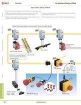
AS-Interface safety at work integrates a safety network into one wire-saving system.Safety slaves and safety monitors can be simply connected to the existing AS-Interface network to establish the AS-Interface Safety at Work.Interlock switches, safety relay modules and other safety components can be connected to the safety network via safety slaves.ՕEmergency stop switches can be connected directly to AS-Interface Safety at Work, further reducing wiring.Safety components can be connected to other networks through gateways.Օ OverviewX Series E-StopsDoor Interlock Switches Enabling SwitchesBarriersAS-Interface...
Open the catalog to page 2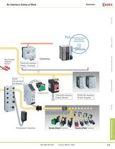
OverviewX Series E-StopsDoor Interlock SwitchesEnabling SwitchesBarriersAS-Interface Safety at Work
Open the catalog to page 3
OverviewX Series E-StopsDoor Interlock Switches Enabling SwitchesBarriersAS-Interface Safety at Work AS-Interface SafetyCommunication TerminalAS-InterfaceSafety Monitor > ProductDescriptionPart Number SX5A AS-Interface Safety Communication Terminal (Safety Slave)2 inputs (safety input) SX5A-AWN20 Base ModuleUsed with AS-Interface safety communication terminal SX5A-G1FA SX5A AS-Interface Safety Monitor2 safety outputs x 2 circuits SX5A-MBR02 > ProductDescriptionPart Number Safety Monitor Confi guration SoftwareCD-ROM SX9Y-ASMTRCable For connecting the safety monitor and PC SX9Z-PCCABLEFor connecting...
Open the catalog to page 4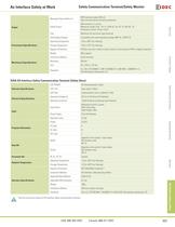
Message Output (safety on)PNP transistor output 200 mAShort-circuit/reverse connection protectionSafety Output2NO contacts x 2 circuitsMaximum contact load AC-15: 230V AC, 3A, DC-13: 24V DC, 1A Continuous current: 3A per circuitFuseMaximum 4A slow-blow type (external) Overvoltage Category3 (complies with rated operating voltage 300V AC, VDE0110) Output > OverviewX Series E-StopsDoor Interlock SwitchesEnabling SwitchesBarriersAS-Interface Safety at Work Operating Temperature20 to +60ְC (no freezing)Storage Temperature30 to +70ְC (no freezing) Degree of ProtectionIP20 (for use only in electric...
Open the catalog to page 5
NameSpecificationPart Number XA/XW Series IDC Connector Kit End connector (with cover) XW9Z-C100-1Through connector (with cover)XW9Z-C100-2IDC Connector Termination Tool Manufactured by ITW Pancon MMIT-156FCrimping Type Connector CableLength 500 mm, with one connectorXW9Z-C205Length 1m, with one connectorXW9Z-C210FB Series Control StationM12 Connector CableLength 300 mm, straight FB9Z-CS03Length 1m, straightFB9Z-CS10 Length 2m, straightFB9Z-CS20 Length 1m, right-angleFB9Z-CL10 Length 2m, right-angleFB9Z-CL20Hand-held Programming Device > 1 OverviewX Series E-StopsDoor Interlock Switches Enabling...
Open the catalog to page 8
Operating ForcePushlock: 10.5N (XA series), 32N (XW, FB series)Pull reset: 10N (XA series), 21N (XW, FB series) Turn reset: 0.16Nm (XA series), 0.27 Nm (XW, FB series)Miniumum Force Required for Direct Opening Action60N (XA series), 80N (XW, FB series)Minimum Operator Stroke Required for Direct Opening Action4.0 mmMaximum Operating Stroke4.5 mmOperating Frequency900 operations/hour Mechanical Life250,000 operations minimum Electrical Life250,000 operations minimumConnectorsIDC connector (XA series)IDC connector, crimping connector (XW series) M12 connector/AS-Interface piercing connector (FB...
Open the catalog to page 9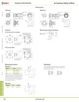
29.6 OverviewX Series E-StopsDoor Interlock Switches Enabling SwitchesBarriersAS-Interface Safety at Work 33.6 4-M4 Tapping Screw Holes for Rear Mounting (Depth: 10 mm) 2-Front Mounting Holes14 Knockout > 21 4121 76.0 2-4.6 76.0 踢ȗ 59.5 15.5 ∗ Without nameplate: 32 With nameplate: 33.5 62 >
Open the catalog to page 10
Wiring and Installation Panel Mounting > OverviewX Series E-StopsDoor Interlock SwitchesEnabling SwitchesBarriersAS-Interface Safety at Work Before wiring the interface cable, discharge static electricity. Tighten the screws to a torque of 0.8 to 1.2 Nm.The AS-Interface power supply unit must separate the main power (input) and output safely according to IEC 60742. It must also maintain a stable supply in the event of instantaneous power failure. The panel thickness should be within the range from 0.8 to 6.0 mm. Remove the locking ring from the operator and check that the rubber gasket is in...
Open the catalog to page 11
OverviewX Series E-StopsDoor Interlock Switches Enabling SwitchesBarriersAS-Interface Safety at Work
Open the catalog to page 12All IDEC catalogs and technical brochures
 MACHINE TOOLS Industry Solutions
28 Pages
 ROBOTICS Industry Solutions
27 Pages
 Relay Selection Guide
16 Pages
 PUSH-IN PRODUCTS
12 Pages
 PRODUCT GUIDE
44 Pages
 HR6S
HR6S32 Pages
 KW2D SERIES
16 Pages
 LED-Leuchten: LF2B
6 Pages
 LED Illumination Units
28 Pages
 LED-Leuchten: LF1B-N
4 Pages
 Katalog FL1E
16 Pages
 RS485-Kommunikationsmodul
2 Pages
 Automation Organizer
2 Pages
 Web-Server-Modul
4 Pages
 MicroSmart DC12V
4 Pages
 FT1A SmartAXIS
36 Pages
 RTE/GT3/GE1A/GT5P/GT5Y
68 Pages
 Universalrelais RR/RY/RH/RU
59 Pages
 RJ.S Relays und Sockets
12 Pages
 RV8H-Baureihe
6 Pages
 E-Stop Switches
16 Pages
 XA series
7 Pages
 High Performance
4 Pages
 HG1X
HG1X3 Pages
 FL1E
FL1E4 Pages
 product brochure
6 Pages
 All Product Brochure
6 Pages
 Complete Contactors Catalog
60 Pages
 Complete Terminal Blocks Catalog
22 Pages
 Complete Timer Catalog
68 Pages
 Complete Relay & Socket Catalog
68 Pages
 Complete Display Lights Catalog
44 Pages
 Complete Safety Overview
6 Pages
 Complete Power Supply Catalog
22 Pages
 Complete O/I Catalog
22 Pages
 Complete PLC Catalog
68 Pages



- DC power supply
- AC/DC power supply
- Rectangular housing
- Ethernet switch
- Electric gearmotor
- Industrial network switch
- LED lighting
- Plastic housing
- Single-pole switch
- Windows software
- Cloud-based software
- Push-button switch
- Waterproof network switch
- Power supply for industrial applications
- Switched-mode power supply
- Unmanaged switch
- Photoelectric sensor
- Compact power supply
- Indoor enclosure