Circuit Breakers Catalog

Circuit Breakers Catalog
Catalog excerpts
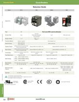
Circuit Breakers Selection Guide Signaling Lights Switches & Pilot Lights Selection Guide Series NC1V NRBM NRC Appearance Page Relays & Sockets NRA Visit www.IDEC.com/circuitbreaker 923 Actuator Style Lever Lever and Rocker (non-illuminated and illuminated) Number of Poles 1, 2, 3 Lever: 1, 2, 3 Rocker: 1 Lever Slide switch, lever 1, 2, 3 1, 2 Hydraulic magnetic Electromagnetic trip Internal Circuits Series current trip Relay voltage trip Series current trip Auxiliary Contact Timers Protection Method Optional 125V AC 3A (resistive load), 30V DC 2A (resistive load) Optional (250V AC, 5A; 50V DC,...
Open the catalog to page 2
Circuit Breakers NC1V Switches & Pilot Lights NC1V Circuit Breakers Key features: Signaling Lights • Superior protection for a wide range of devices from sensitive electronic equipment to electrical control circuits. Applications include semiconductor manufacturing equipment, electronic controllers, computers, microprocessors, communications equipment, power supplies, machine tools, motors, and more. • Excellent tripping time curve performance • Flat retractable lever for safety operations • Slim housing design • Spring-up terminals allow for use of ring terminals • Fingersafe main circuit terminals...
Open the catalog to page 3
Circuit Breakers Switches & Pilot Lights NC1V Specifications Operator Style Retractable lever Internal Circuit Series trip (current trip), Relay trip (voltage trip) Protection Method Hydraulic magnetic tripping system, Magnetic tripping system (voltage trip) 2-pole 3-pole 250V AC 50/60Hz, 65V DC 250V AC 50/60Hz, 125V DC 250V AC, 50/60Hz Rated Short-circuit Capacity Signaling Lights 1-pole Rated Voltage (AC/DC)1 Relays & Sockets No. of Poles 250V AC, 2500A 65V DC, 2500A 250V AC, 2500A 125V DC, 2500A 250V AC, 2500A Rated Current 0.1A, 0.3A, 0.5A, 1A, 2A, 3A, 5A, 7A, 10A, 15A, 20A, 25A, 30A Operation...
Open the catalog to page 4
Circuit Breakers NC1V Specify rated current, time delay curve, or voltage trip coil voltage in place of Internal Circuit No. of Poles Inertial Delay Auxiliary Contact Alarm Contact — 6 7 8 Code NC1V-1100F- 6 7 One Auxiliary Contact NC1V-1111F- 6 7 NC1V-1121F- 6 7 NC1V-2100- 6 7 NC1V-2111- 6 7 Two Auxiliary Contacts NC1V-2112- 6 7 One Alarm Contact NC1V-2121- 6 7 One Auxiliary Contact and One Alarm Contact NC1V-2131- 6 7 — NC1V-2100F- 6 7 One Auxiliary Contact Two Auxiliary Contacts NC1V-2112F- 6 7 One Alarm Contact NC1V-2121F- 6 7 One Auxiliary Contact...
Open the catalog to page 5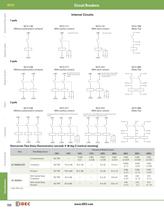
Circuit Breakers Switches & Pilot Lights NC1V Internal Circuits 1-pole NC1V-1100 (Without auxiliary/alarm contacts) NC1V-1111 (With auxiliary contact) LINE LINE NC1V-1121 (With alarm contact) LINE One auxiliary contact. NC1V-1500 (Relay Trip) A One alarm contact. Signaling Lights B C D LOAD LOAD C N O N C C LOAD N O N C Relays & Sockets 2-pole NC1V-2100 (Without auxiliary/alarm contacts) LINE NC1V-2111 (With auxiliary contact) LINE NC1V-2121 (With alarm contact) LINE One auxiliary contact. Also LINE LINE One alarm contact. Also available LINE available with two auxiliary contacts NC1V-2500 (Relay...
Open the catalog to page 6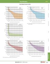
Circuit Breakers NC1V 1000 DC (Note) AC 100 1000 Curve A (medium) Time in sec 10 1 0.1 0.1 0.01 Signaling Lights 1 Curve M (slow) AC 100 10 Time in sec DC (Note) Switches & Pilot Lights Time Delay Curves at 40°C 0.01 100 200 300 400 500 600 700 800 900 100 1000 Current (percent load of the rated current) 1000 Curve S (instantaneous) DC (Note) 100 200 125 300 400 500 600 700 800 900 1000 Relays & Sockets 125 Current (percent load of the rated current) Note: The entire shaded area applies to AC. For DC, the shaded area on the right of the dashed line applies. 1 Timers Time in sec 10 AC 0.1 0.01...
Open the catalog to page 7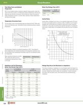
Circuit Breakers Switches & Pilot Lights NC1V Time Delay Curve and Ambient Temperature Relay Trip (Voltage Trip) at 25°C NC1V circuit breakers employ a hydraulic magnetic tripping system, where the rated current (trip current) is not affected by ambient temperatures. But the time delay may vary with the oil viscosity in the oil dash pot. Lower oil viscosity at higher temperatures results in a shorter delay, whereas at lower temperatures the delay will be longer. For DC Resistance (Ω) Tripping Voltage 24-48V 100.0 Tolerance: ±25% Inertial Delay Signaling Lights Temperature Correction Curve The...
Open the catalog to page 8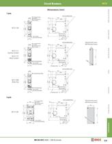
Circuit Breakers NC1V Switches & Pilot Lights Dimensions (mm) 1-pole M4 Terminal Screw (up to 20A) M5 Terminal Screw (25A or more) 12.0 66.0 48.3 78.8 2-ø4.5 Holes (for screw mounting) M4 Terminal Screw (up to 20A) M5 Terminal Screw (25A or more) Signaling Lights ON 17.5 DIN Rail (BNDN1000) 6.6 72.5 44.0 NC1V-1100 71.4 56.0 12.0 5.0 33.0 DIN Rail (BNDN1000) 6.6 66.0 48.3 Mounting Hole Layout (M4 Mounting Screws) Relays & Sockets 12 71.4 ON 78.8 48.4 72.5 NC1V-1121 (Alarm Contact) 71.4 56.0 NC1V-1111 (Auxiliary Contact) 2-M M3.5 Terminal Screw 17.5 4 2-ø4.5 Holes (for screw mounting) 5.0 33.0...
Open the catalog to page 9
Circuit Breakers 2-pole NC1V-2111 (one auxiliary contact) DIN Rail (BNDN1000) M4 Terminal Srew (up to 20A) M5 Terminal Screw (25A or more) 6.6 66.0 48.3 NC1V-2131 (one auxiliary contact and one alarm contact) ON 35.0 78.8 44.0 72.5 NC1V-2112 (two auxiliary contacts) NC1V-2121 (one alarm contact) Signaling Lights 29.5 71.4 56.0 Switches & Pilot Lights NC1V Mounting Hole Layout (M4 Mounting Screws) 29.5 2-ø4.5 Holes (for screw mounting) 5.0 33.0 Dimensions shown are for NC1V-2111 and NC1V-2121. 66.0 4 M3.5 Terminal Screw 2-ø4.5 Holes (for screw mounting) 78.8 ON 35.0 2-M 48.3 72.5 48.4 56.0 NC1V-2500...
Open the catalog to page 10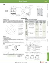
Circuit Breakers NC1V DIN Rail (BNDN1000) 6.6 66.0 M5 Terminal Screw (30A) ON 78.8 48.4 47.0 72.5 71.4 56.0 NC1V-3500 (Relay Trip) Mounting Hole Layout (M4 Mounting Screws) 48.3 71.4 47.0 Switches & Pilot Lights 3-pole 4 2-ø4.5 Holes (for screw mounting) 52.5 Signaling Lights 2-M M3.5 Terminal Screw Terminal Cover 5.0 33.0 Instructions 100% 90% 100% DIN Rails Tightening Torque (N·m) 0.25 to 1.65 Spring-up, fingersafe, slotted Phillips screw with square washer (up to 20A) Applicable Crimping Terminal R1.25-4 1 to 1.4 1.04 to 2.63 R5.5-4 0.25 to 1.65 R1.25-5 1.04 to 2.63 R2-5 2.63 to 6.64 R5.5-5...
Open the catalog to page 11All IDEC catalogs and technical brochures
 Web Server Module
2 Pages
 IDEC FL1D SmartRelay
12 Pages
 MicroSmart
28 Pages
 AP22M Series
4 Pages
 IDEC E-S top Switches
6 Pages
 Complete Contactors Catalog
60 Pages
 Complete Terminal Blocks Catalog
22 Pages
 Complete Timer Catalog
52 Pages
 Complete Relay & Socket Catalog
76 Pages
 Complete Display Lights Catalog
44 Pages
 Complete Safety Overview
4 Pages
 Sensor catalog
55 Pages
 Complete Power Supply Catalog
20 Pages
 Complete O/I Catalog
29 Pages
 Complete PLC Catalog
64 Pages
 All Product Brochure
6 Pages


- Display module
- LCD display panel
- LED lighting
- Single-pole switch
- Windows software
- IO module
- Junction block
- Level probe
- Push-button switch
- Liquid level sensor
- Switching relay
- Analog I/O
- Technology switch
- Multipole switch
- Photoelectric sensor
- Programmable logic controller
- Programming software
- Touch screen HMI
- Electromechanical switch
- Electromechanical relay