


YS Series Contactors Catalog

YS Series Contactors Catalog
This document serves as a comprehensive guide for selecting IEC contactors and related components, covering non-reversing and reversing contactors, thermal overload relays, starters, and accessories.
Details are provided for both AC and DC controlled non-reversing (YS1N, YS3N) and reversing contactors (YS1R, YS3R).
The YS1T-RHA model is highlighted for its specifications and applications.
The document outlines technical parameters for contactors, starters, overload relays, and accessories, including dimensions, mounting, and wiring diagrams.
These contactors are compact, rugged, and comply with international standards. They feature advanced design elements like special silver-alloy contacts and environmentally safe, cadmium-free materials.
Snap-on accessories such as auxiliary contact blocks, adjustable thermal overloads, and PLC interface modules are available.
Detailed ordering information is provided, including product series, coil voltage, maximum current, and auxiliary contact configuration.
References to additional web resources for product information and tools are included.
Detailed specifications for IEC contactors include coil voltage, resistance, and operating times. Electrical life curves and mounting specifications are also provided.
Information on exciting current, pick-up voltage, drop-out voltage, and power consumption for DC-operated contactors is detailed.
Characteristics include contact configuration and rated operational current for AC and DC circuits.
Instructions for selecting and setting reset modes for thermal overload relays are included.
Tripping curves and AC ratings per EN and UL standards are specified, along with wire size specifications for auxiliary contacts.
Instructions for assembling auxiliary contact blocks and mounting/removing surge suppressor modules are provided.
Specifications include input and output characteristics, dimensions, and mounting procedures.
Details on mechanical interlock blocks and connector kits for reversing contactors are provided.
Guidelines for using contactors in various electrical systems, including DC motors and transformers, are detailed.
The document emphasizes selecting contactors with appropriate capacities for high inrush current applications.
Tables provide data on motor power ratings, full load currents, and capacitor-switching applications.
The necessity of confirming actual full load current for accurate selection of contactors and relays is highlighted, along with contact information for further assistance.
Catalog excerpts

Selection Guide IDEC YS Series Contactors / Starters IDEC YS Series Contactors are used in switching motor loads. Like allIDEC products, each model is engineered for long life, minimum mainte- nance, dependable operation, and superior performance.Snap on accessories are available for the IDEC YS series, giving eachmodel the flexibility to meet any application requirement.1. Auxiliary contact blocks 2. Adjustable thermal overloads 3. Surge suppressor modules 4. Mechanical interlock blocks 5. PLC interface modules Top mounting type (2 or 4 poles type) ՕSide mounting type (2 poles type) > IEC Contactors...
Open the catalog to page 2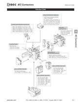
(With Surge Suppressor Module)YS9Z-TCU500UH > The interface module incorporates con-tacts which are actuated upon energiza- tion of the module from low power 24VDC sources such as outputs from sensors and programmable controllers. for YS1N-80F to -125FYS9Z-TU180 for YS1N-150F to -180FYS9Z-TU300 for YS1N-220F to -300F For reversing applicationsYS1R, AC Controlled YS3R, DC Controlled(reversing type) Used for reversing contactorsYS9Z-TMI65 for YS1N-9F through 65F YS9Z-TMI125 for YS1N-80F through 300F > IEC Contactors
Open the catalog to page 3
Completed Part Number of Contactors1 Product Series YS1N: Non- reversing contactor, AC controlled YS1R: Reversing contactor, AC controlled YS3N: Non-reversing contactor, DC controlled YS3R: Reversing contactor, DC controlled4 Coil Voltage 2 a) Approximate Maximum AC3 Current AC or DC Controlled Contactors D024 : DC 24V 9:9A, 12:12A, 20:20A, 25:25A, 32:32A, 38:38A, 40:40A, 50:50A, 65:65A, 80:80A, 100:100A, 125:125A AC Contactors Only 150:150A, 180:180A, 220:220A, 300:300A (Other Voltages Available, Contact IDEC)A600 : AC600V 50/60HzD110 : DC 110VD220 : DC 220V M100 : DC 110V M200 : DC 220VD048...
Open the catalog to page 4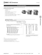
Notes: 1. Use the above ordering information only when interpreting part numbers. Do not use for developing part numbers. 2. For applicable combinations of contactors and thermal overload relays, please consult following page. 3. For specifications and settings please see pages D-16 through D-34. >
Open the catalog to page 9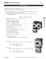
Completed Part Number of Reversing Starter1 Product Series YS2N AC non-reversing StarterYS1R contactor ----> YS2R AC reversing StarterYS3N contactor ----> > IEC Contactors YS4N DC non-reversing StarterYS3R contactor ----> YS4R DC reversing Starter F: is replaced by size, 9-300 for AC controlled FG2: is replaced by size, 9-65 for DC controlled FG: is replaced by size, 80-125 for DC controlled 01: with 1NC, for contactor sizes 9F-12F 10: with 1NO, for contactor sizes 9F-12F 11: with 1NO-1NC, for contactor sizes 20F-65F 22: with 2NO-2NC, for contactor sizes 80F-300F YS1N contactor ----> 5 Coil Voltage...
Open the catalog to page 11
Accessory Description Part Number > each part number is for ONE (1) main contact Stationary Main Contacts > For use with YS-20FYS9Z-KIF409056-AFor use with YS-25FYS9Z-KIF409057-A For use with YS-32FYS9Z-KIF410179-A For use with YS-38FYS9Z-KIF410180-A For use with YS-40FYS9Z-KIF409083-A For use with YS-50FYS9Z-KIF409083-B For use with YS-65FYS9Z-KIF409083-C For use with YS-80FYS9Z-KIF410697-A For use with YS-100FYS9Z-KIF410697-B For use with YS-125FYS9Z-KIF410697-C For use with YS-150FYS9Z-KIF410853-A For use with YS-180FYS9Z-KIF410854-A For use with YS-220FYS9Z-KIF411841-A For use with YS-300FYS9Z-KIF411842-A...
Open the catalog to page 14
Part Number Description For Use WithBAA1000 > 35mm Aluminum DIN Rail 7.5 mm deep1 meter longYS1N-9F through YS1N-38F Contactors BNDN1000 > 35mm Aluminum DIN Rail 10.5 mm deep. 1 meter longYS1N-9F through YS1N-38F Contactors IEC Contactors YS9Z-TIP66 Markers > Plastic replacement markerssold in 100 piece packsYS-9F through YS-65F series contactors, overloads relays and top mount auxiliary contact blocks. BNL8 > DIN Rail End Stop used to prevent contactors from sliding on DIN rails YS1N-32F/YS1N-38F & YS1R reversing contactors BNL5 > DIN Rail End Stop used to prevent contactors from sliding on...
Open the catalog to page 15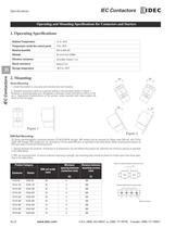
Ambient Temperature > -5 to +40аC Temperature inside the control panel > -5to +55аC Relative humidity > 45% to 85% RH Altitude > No more than 2,000m Vibration resistance > 10 to 50Hz 19.6m/s 2 ( 2G ) Shock resistance > 49.0m/s 2 (5G) Storage temperature > -40C to +70аC 30 30 а 30 Direct Mounting 1. Install the product in a dry area with minimal dust and vibration.2. Standard mounting is done on a vertical surface in the directions shown in Figure 1. However, a mounting angle up to 30 degrees is allowed in each direction as shown in Fig- ure 2. Operational characteristics of the product, when...
Open the catalog to page 22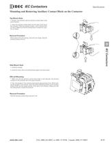
Top Mount Style Removal Procedure Side-Mount StyleDIN rail Mounting Removal Procedure 1. Position the contactor and the auxiliary contact block in thesame direction.2. Insert the auxiliary contact block into the area of the top ofthe contactor. Slide the auxiliary contact until it bottoms (Do not force.) Make sure that the locking hook is locked into posi- tion as shown While lightly lifting the locking hook with your finger, slide theauxiliary contact unit out. 1. Contactor plunger2. Inside this area, there are locking hooks (upper and lower areas)1. Make sure that the auxiliary contact block...
Open the catalog to page 29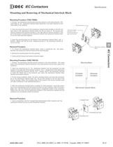
Mounting Procedure (YS9Z-TMI65) Removal ProcedureMounting Procedure (YS9Z-TMI125) Removal Procedure 1. Position the mechanical interlock block and the contactor in the same direction. (Thename plate of the mechanical interlock block should be in the same direction as the name plate of the contactor.2. Insert the connection pins of the mechanical interlock block (located on the left andright sides of the mechanical interlock block) into the pin holes of the forward and reverse contactors (the forward contactor in the right and the reverse contactor in the left in the picture). Carefully push the...
Open the catalog to page 33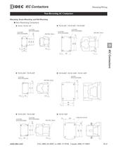
2-4.8 DIA. MTG HOLES(M4) 2-4.8 DIA. MTG HOLES(M4) 2-4.8 DIA.MTG HOLES(M4) 2-4.8 DIA. MTG HOLES(M4) DIN RAIL 75mm 2-4.8 DIA.MTG HOLES(M4) > 15.5 DIN RAIL 35mm > 6 AB B 52 95100 34535 4.5 > IEC Contactors A 7655 >
Open the catalog to page 43
MaximumOperationalCurrent AC1 Instantaneous Auxiliary Contacts Category AC1(Star Connection) Completed Part Number 220V 230V 380V 400V 415V 440V 500V 660V 690V NO NCkWkWkWkWkWkWA > IEC Contactors
Open the catalog to page 51All IDEC USA catalogs and technical brochures
 LD6A
LD6A8 Pages
 LF2B LED Illumination Units
6 Pages
 A series Switches & Pilot Lights
40 Pages
 BA Series Terminal Blocks
52 Pages
 EF1A Flameproof LED
24 Pages
 TWS series
40 Pages
 H6 Series
28 Pages
 Complete PLC Catalog
64 Pages
 Complete Terminal Blocks Catalog
22 Pages
 Complete Timer Catalog
52 Pages
 Complete Relay & Socket Catalog
76 Pages
 Complete Safety Overview
4 Pages
 Complete Power Supply Catalog
20 Pages
 Complete O/I Catalog
29 Pages
 All Product Brochure
6 Pages


Archived catalogs
 YC Series Contactors Catalog
24 Pages
 Lumifa LED Light Catalog
8 Pages
 All Product Brochure
2 Pages
 Complete Display Lights Catalog
44 Pages

- Power supply unit
- DC power supply
- AC/DC power supply
- Single-pole switch
- Junction block
- Push-button switch
- Technology switch
- Multipole switch
- DIN rail power supply
- Electromechanical switch
- DIN rail-mounted terminal block
- Rotary electric switch
- Rocker switch
- IP67 switch
- Signal tower light
- Illuminated push-button switch
- LED stack light
- Touch push-button switch
- Action push-button switch
- Form push-button switch