A series Switches & Pilot Lights
1 /40Pages

A series Switches & Pilot Lights
1 /40Pages
Catalog excerpts
A series Switches & Pilot Lights [dec Think Automation and beyond... IDEC CORPORATION
Open the catalog to page 1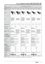
A Series Selection Guide 016 012 010 08 A Series Selection Guide 016 012 010 08 A Series Switches and Pilot Lights Mounting Hole Size Illuminated Pushbuttons (Momentary, Maintained) Pilot Light Pushbuttons (Momentary, Maintained) Illuminated Pushbuttons (Momentary, Maintained) Pilot Light Pushbuttons (Momentary, Maintained) Illuminated Pushbuttons (Momentary, Maintained) Pilot Light Pushbuttons (Momentary, Maintained) Bezel Color Light Source LED lamp (IDEC’s LAD-S) LED lamp (IDEC’s LAD-S) LED lamp (IDEC’s LAD-S) Button/Illumination Color Illumination: amber, green, red, white, yellow Button:...
Open the catalog to page 3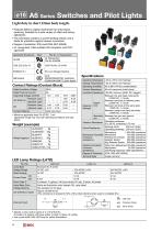
Light duty in short 22mm body length. • Features IDEC’s original mechanism for snap-action switching. Suitable for a wide variety of office and factory aplications. • The LED lamp contains a current-limiting resistor and a diode for protection against reverse connection. • Degree of protection: IP40 and IP65 (IEC 60529) • UL recognized, CSA certified, EN compliant, and CCC approved. Applicable Standards Specifications Contact Ratings (Contact Block) Rated Insulation Voltage • Minimum applicable load: 5V AC/DC, 1 mA (applicable range may vary with operating conditions and load types) Weight (example)...
Open the catalog to page 4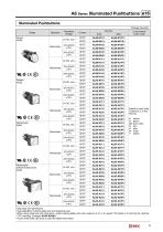
• See page 7 for dimensions. • See page 20 for marking plate size and engraving area. • When using white lens unit (clear lens + white marking plate) with color codes A, G, R, or S, specify “W” before © in the Part No. (without CCC marking) Example: AL6H-M24W© • A pure white (JW) LED lamp is used for yellow illumination.
Open the catalog to page 5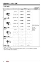
• See page 7 for dimensions. • See page 20 for marking plate size and engraving area. • When using white lens unit (clear lens + white marking plate) with color codes A, G, R, or S, specify “W” before © in the Part No. (without CCC marking) Example: AL6H-M24W© • A pure white (JW) LED lamp is used for yellow illumination.
Open the catalog to page 6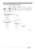
A6 Series Illuminated Pushbuttons and Pilot Lights Dimensions ø16 Dimensions (Illuminated Pushbuttons & Pilot Lights) Terminal Width 2.8×0.5t 3 Panel Thickness 0.5 to 6 Rectangular Rectangular w/3-way barrier (TOP) Locking Ring Rubber Gasket Anti-rotation Ring Pilot Light Illuminated Pushbutton Terminal Arrangement (bottom view) Illuminated Pushbutton Pilot Light Lamp Terminal (–) Lamp Terminal (–) With contact: NC1, NO1, C1 terminal only Mounting Hole Layout Round/Square +0.2 0 Note: Determine mounting centers to ensure easy operation. Rectangular Rectangular w/3-way barrier
Open the catalog to page 7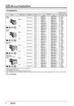
• Specify a color code in place of ® or © in the Part No. • See page 9 for dimensions. • See page 20 for marking plate size and engraving area. • Black is available for lens style buttons. Black lens consists of a clear lens and a black marking plate. Specify “B” in place of © in the Part No. Example:AB6H-M2LB
Open the catalog to page 8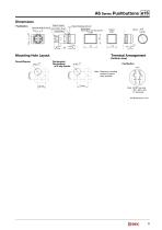
A6 Series Pushbuttons ø16 Dimensions Rubber Gasket Terminal Width 2.8×0.5t Anti-rotation Ring 2.5 3 Locking Ring Panel Thickness 0.5 to 6 Rectangular Rectangular w/3-way barrier (TOP) Mounting Hole Layout Terminal Arrangement (bottom view) Rectangular Rectangular w/3-way barrier Note: Determine mounting centers to ensure easy operation. Note: SPDT has only NC1, NO1, and C1 terminals. All dimensions in mm.
Open the catalog to page 9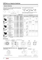
How to change the operator position Pull out the bezel to release the lock. Rotate the bezel, and push it in at 45° intervals to lock the bezel. Operator position can be changed by IDEC’s original bezel rotating and locking system. The bezel can be locked at every 45° and bezel rotation is prevented while mounting on a panel. Example: 3-position • Bezel: black • Knob: black Contact Operation Terminal Arrangement (bottom view) (Selector Switch) (top) Mounting Hole Layout Round/Square 0l6.2+0'2 Note: Determine mounting centers to ensure easy operation. All dimensions in mm.
Open the catalog to page 10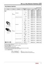
• Specify the key code in place of □ in the Part No.: T (disc tumbler key), S (wave key) • For contact operation, see page 14. • Key is retained at • positions and removable at O positions. • Two keys are supplied. • The front of key cylinder is made of metal. • For disc tumbler key, only one type of key is available. • For wave key, besides the standard key (key number 0H), six other keys are also available. To order other keys, specify the key number as shown below: Note: Key number is indicated on the key cylinder. Standard keys do not have a key number indication.
Open the catalog to page 11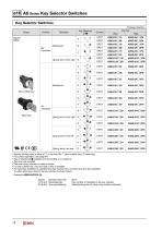
• Specify the key code in place of □ in the Part No.: T (disc tumbler key), S (wave key) • For contact operation, see page 14. • Key is retained at • positions and removable at O positions. • Two keys are supplied. • The front of key cylinder is made of metal. • For disc tumbler key, only one type of key is available. • For wave key, besides the standard key (key number 0H), six other keys are also available. To order other keys, specify the key number as shown below: Note: Key number is indicated on the key cylinder. Standard keys do not have a key number indication.
Open the catalog to page 12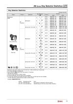
• Specify the key code in place of □ in the Part No.: T (disc tumbler key), S (wave key) • For contact operation, see page 14. • Key is retained at • positions and removable at O positions. • Two keys are supplied. • The front of key cylinder is made of metal. • For disc tumbler key, only one type of key is available. • For wave key, besides the standard key (key number 0H), six other keys are also available. To order other keys, specify the key number as shown below: Note: Key number is indicated on the key cylinder. Standard keys do not have a key number indication.
Open the catalog to page 13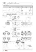
ø16 A6 Series Key Selector Switches Contact Operation Operator Position & Contact Operation (Top View) Positions Spring return from right DPDT Maintained Spring return from right Spring return from left Spring return two-way C Left Right Contact Contact NO NC NO NC Left Right Contact Contact NO NC NO NC C Left Right Contact Contact NO NC NO NC Left Right Contact Contact NO NC NO NC Left Right Contact Contact NO NC NO NC Right Contact Left Contact Rubber Gasket Terminal Width 2.8×0.5t Locking Ring Anti-rotation Ring Locking Ring Anti-rotation Ring Terminal Arrangement (bottom view) (Key Selector...
Open the catalog to page 14All IDEC USA catalogs and technical brochures
 LD6A
LD6A8 Pages
 LF2B LED Illumination Units
6 Pages
 BA Series Terminal Blocks
52 Pages
 EF1A Flameproof LED
24 Pages
 TWS series
40 Pages
 H6 Series
28 Pages
 Complete PLC Catalog
64 Pages
 Complete Terminal Blocks Catalog
22 Pages
 Complete Timer Catalog
52 Pages
 Complete Relay & Socket Catalog
76 Pages
 Complete Safety Overview
4 Pages
 Complete Power Supply Catalog
20 Pages
 Complete O/I Catalog
29 Pages
 All Product Brochure
6 Pages


Archived catalogs
 YC Series Contactors Catalog
24 Pages
 Lumifa LED Light Catalog
8 Pages
 All Product Brochure
2 Pages
 YS Series Contactors Catalog
60 Pages
 Complete Display Lights Catalog
44 Pages

- SARRALLE power supply
- SARRALLE DC power supply
- SARRALLE AC/DC power supply
- Single-pole switch
- Junction block
- Push-button switch
- Technology switch
- SARRALLE multipole switch
- SARRALLE DIN rail power supply
- Electromechanical switch
- Rotary electric switch
- DIN rail-mounted terminal block
- Rocker switch
- Signal tower light
- IP67 switch
- Illuminated push-button switch
- LED stack light
- Touch push-button switch
- Touch switch
- Action push-button switch