


Complete X Series E-Stops Catalog

Complete X Series E-Stops Catalog
The XW Series E-Stops by IDEC feature a unique "Safe Break Action" design that ensures Normally Closed (NC) contacts open if the switch is damaged or subjected to excessive force, enhancing safety during emergencies. This design is specific to the XA, XW, and XN series.
Innovative Design and Safety Features
Unlike traditional E-Stop switches that rely on spring pressure, the "Safe Break Action" ensures contacts open even if welded, providing reliable machine stoppage. These switches are suitable for Level 4 safety applications and offer up to four contacts in a compact form.
Padlock E-Stops
The XN4E series allows technicians to secure the E-Stop with personal padlocks, preventing unauthorized resets and ensuring all locks are removed before restarting the machine.
Specifications and Features
The XW Series E-Stops are available in 22mm sizes with features such as:
- 48.7 mm depth behind the panel for both illuminated and non-illuminated units.
- Push-to-lock, Pull or Turn-to-reset mechanisms.
- Safety lock mechanism compliant with IEC60947-5-5 standards.
- IP65 protection for operators and IP20 for terminals.
- Available in ø40 and ø60 mm button sizes.
- RoHS compliant and UL listed.
Technical Specifications
Key specifications include:
- Rated Insulation Voltage: 250V
- Rated Thermal Current: 2.5A
- Operating Temperature: -25 to +60°C for non-illuminated, -25 to +55°C for illuminated
- Mechanical Life: 250,000 operations minimum
- Electrical Life: 100,000 operations minimum
Part Numbers and Configurations
Detailed part numbers are provided for various configurations, including non-illuminated and illuminated units, different contact configurations, and sizes.
Conclusion
The XW Series E-Stops by IDEC offer advanced safety features and robust design suitable for high-stress environments, ensuring reliable operation and enhanced safety in emergencies.
The emergency stop switch is properly assembled when the bayonet ring is in place. The LED unit can be removed using the LED unit removal tool (MT-101) and installed by aligning the top of the LED unit with the TOP marking on the contact block.
Wiring Instructions
Use a wire size of 16 AWG maximum. Solder the terminal at 310 to 350°C within 3 seconds using Sn-Ag-Cu solder. Avoid applying tensile force or bending the terminals. Use non-corrosive rosin flux and protective tubes to prevent short circuits.
PC Board Terminal Type
Ensure sufficient space for rotating the PC board when mounting a contact block. Use glass epoxy copper-clad laminated sheets of 1.6 mm thickness for PC boards. The minimum applicable load is 5V AC/DC, 1 mA.
Installing Insulation Terminal Cover
Align the TOP marking on the terminal cover with the contact block and press the cover toward the block. Insert wires into the terminal cover holes before soldering.
Contact Bounce
Consider contact bounce time (reference value: 20 ms) when designing a control circuit.
Safety Precautions
Turn off power before installation, removal, wiring, maintenance, and inspection to avoid electrical shock or fire hazards. Use the LED unit removal tool to prevent burns.
Specifications
Complies with IEC60947-5-1, EN60947-5-1, IEC60947-5-5, EN60947-5-5, UL508, UL991, CSA C22.2 No. 14. Operating temperature ranges from -25 to +60°C for non-illuminated and -25 to +55°C for illuminated models. The degree of protection is IP65.
Contact Ratings
Rated insulation voltage is 250V, and rated current is 5A. The rated operating voltage varies with different load types.
Operating Instructions
To remove the contact block, unlock the operator button, pull back the bayonet ring, turn the contact block counterclockwise, and pull out. To install, align markings, press the contact block onto the operator, and turn clockwise until the bayonet ring clicks.
Accessories
Includes locking ring wrench, locking ring twist wrench, lockout hasp, terminal cover for contact block, and IP20 fingersafe cover.
- Align the TOP marking on the cover with the TOP marking on the contact block and press the cover toward the contact block.
- Once installed, the XW9Z-VL2MF cannot be removed and cannot be installed after wiring.
- Crimping terminals cannot be used with the XW9Z-VL2MF; use solid wires instead.
- Ensure the cover is securely installed to achieve IP20 protection and prevent electric shock.
- Tighten M3 terminal screws to a torque of 0.6 to 1.0 N·m.
- Wire thickness should be 0.75 to 1.25 mm² (AWG18 to 16).
- Install an insulating tube on the crimping terminal.
- NC main contacts and NO monitor contacts will bounce when the button is reset or pressed, respectively. Consider a contact bounce time of 20 ms in control circuit design.
- The LED lamp is built into the contact block and is non-replaceable.
- Avoid exposing the switch to excessive shocks and vibrations to prevent deformation or damage.
- Use Tyco Electronics D-2000 series connectors for proper installation.
- Fasten the cable to prevent deformation or damage to the switch.
- Align the side without thread on the operator with the TOP marking and the small s marking on the anti-rotation ring.
Catalog excerpts

Safety Overview XW Series E-Stops Interlock Switches Enabling Switches Safety Control Light Curtains AS-Interface Safety at Work
Open the catalog to page 1
Revolutionary “Safe Break Action” Design The IDEC Emergency Stop switches, the XA, XW, and XN series, include revolutionary new technology that will change the way E-Stop switches are designed. This “safe break action” concept provides greater levels of human safety and is the first of its kind in the world! Conventional E-Stop switches are designed with spring pressure on the Normally Closed (NC) contacts, keeping them in the closed position and allowing the machine to operate. Improper installation or excessive force to the stop button in an emergency may break or dislodge a vital part, causing...
Open the catalog to page 2
Important Safety Information Overview X Series E-Stops have lower internal energy in the “Locked” (Latching) position than in the “Normal” (Reset) position. When the switch is damaged from an excessive shock, the main contact (NC) moves toward the OFF (Safe) position. Direct Opening Action XW Series E-Stops Even if the contacts are welded, the force applied on the button directly opens the contact. Rated Insulation Voltage: 250V Rated Thermal Current: 2.5A Safety Interlock Mechanism Contacts are opened when the operator is locked, and remain opened until the operator is unlocked intentionally....
Open the catalog to page 3
Interlock Switches Selection Guide Series see Switches & Pilot Devices section see Switches & Pilot Devices section Page Mounting Hole Operator Type Illuminated & Non-Illuminated E-Stops: Pushlock/Turn Reset, Push-Pull Reset Action Pushlock Pull or Turn Reset (both actions available in each switch, except XN4E) Contact Configuration Enabling Switches Electrical Life Mechanical Life Termination Degree of Protection Screw Terminals Operator: IP65 (IEC60529) Terminal: IP20 (when XW9Z-VL2MF is installed) AS-Interface Safety at Work Light Curtains Safety Control
Open the catalog to page 4
Operating Force Push-to-lock: 32N Pull-to-reset: 21N Turn-to-reset: 0.27N·m Minimum Force Required for Direct Opening Action Min Operator Stroke Required for Direct Opening Action Maximum Operator Stroke Contact Resistance 50mΩ maximum (initial value) Contact Material Gold plated silver Insulation Resistance Impulse Withstand Voltage Pollution Degree Operation Frequency Shock Resistance Operating extremes: 150m/s2 (15G), Damage limits: 1000m/s2 (100G) Vibration Resistance Operating extremes: 10 to 500Hz, amplitude 0.35mm acceleration 50m/s2 Damage limits: 10 to 500Hz, amplitude 0.35mm acceleration...
Open the catalog to page 5
Part Numbers Overview Operator Type Monitor Contact Main Contact Part Number Interlock Switches 40mm Mushroom LED with built-in 24V AC/DC LED 1. The light is independent of the position of the switch, except for push-on LED type. 2. The light only operates when the switch is pressed as it is internally wired. Enabling Switches XW Series EMO Switches Style Part Number FB Enclosures with XW E-Stops Style Part Number Light Curtains AS-Interface Safety at Work 60mm Push-lock Turn/Pull Reset Non-Illuminated 2NC 40mm Push-lock Turn/Pull Reset Illuminated* 40mm Push-lock Turn/Pull Reset Non-Illuminated...
Open the catalog to page 6
XW Series E-Stops Contact Ratings Mounting Hole Layout Resistive Load (DC-12) 20.1 Inductive Load (DC-13) Gasket Locking Ring Terminal Marking Description • Contact Type 1-2: NC main contact 3-4: NO monitor contact • Contact Number (1-4) Starting with the contact on TOP in a counterclockwise direction. Note: 1: contact on the TOP 2: contact on the Left 3: contact on the Bottom 4: contact on the Right Light Curtains Safety Control Terminal Arrangements (Bottom View) 4NC 1NO-3NC 2NC Voltage Code Blank: Non-illuminated Q4: Illuminated 24V AC/DC Color R: red RH-EMO: red with EMO engraving 1 - 4 contacts,...
Open the catalog to page 7
XW LED Illuminated/Push-ON (with terminal cover) Illuminated Gasket M3 Terminal Locking Ring Screw M3 Terminal M3 Terminal Screw Screw Gasket Gasket Locking Ring Locking Ring Terminal Cover IP20 Protection Cover XW9Z-VL2M XW9Z-VL2MF Interlock Switches Panel Cut-out Enabling Switches Rubber Gasket Locking Ring Terminal Cover XW9Z-VL2MF Panel Thickness 0.8 to 6 Accessories: Terminal Covers Appearance Safety Control Panel Cut-out Gasket Locking Ring Panel Cut-out Panel Cut-out Panel Thickness 0.8 6 Panel Thickness 0.8 toto 6 Panel Thickness 0.8 to 6 Panel Thickness 0.8 to 6 XW Non-Illuminated (with...
Open the catalog to page 8
Operating Instructions Installing the Contact Block First unlock the operator button. Grab the bayonet ring j and pull back the bayonet ring until the latch pin clicks k, then turn the contact block counterclockwise and pull out l. First unlock the operator button. Align the small t marking on the edge of the operator with the small s marking on the yellow bayonet ring. Hold the contact block, not the bayonet ring. Press the contact block onto the operator and turn the contact block clockwise until the bayonet ring clicks. Bayonet Ring Removing the Contact Block p marking XW Series E-Stops k...
Open the catalog to page 9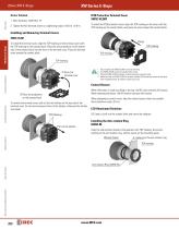
IP20 Protection Terminal Cover XW9Z-VL2MF Screw Terminal 1. Wire thickness: AWG18 to 16 To install the IP20 protection cover, align the TOP marking on the cover with the TOP marking on the contact block, and press the cover toward the contact block. 2. Tighten the M3 terminal screw to a tightening torque of 0.6 to 1.0 N·m. Installing and Removing Terminal Covers Enabling Switches Interlock Switches To install the terminal cover, align the TOP marking on the terminal cover with the TOP marking on the contact block. Place the two projections on the bottom side of the contact block into the slots...
Open the catalog to page 10
Switches & Pilot Devices ø16mm XA E-Stops Switches & Pilot Devices Signaling Lights Relays & Sockets • Two button sizes: ø29 and ø40mm • Lead-free, RoHS compliant, (EU directive 2002/95/EC) • Depth behind the panel: Standard - only 27.9mm for 1 to 4 contacts Unibody - only 23.9mm for 1NC or 2NC • IDEC’s original “Safe break action” ensures that the NC contacts open when the contact block is detached from the operator. • Push-to-lock, Pull or Turn-to-reset operator • Direct opening action mechanism (IEC60947-5-5, 5.2, IEC60947-5-1, Annex K) • Safety lock mechanism (IEC60947-5-5, 6.2) • Degree...
Open the catalog to page 11All IDEC USA catalogs and technical brochures
 LD6A
LD6A8 Pages
 LF2B LED Illumination Units
6 Pages
 A series Switches & Pilot Lights
40 Pages
 BA Series Terminal Blocks
52 Pages
 EF1A Flameproof LED
24 Pages
 TWS series
40 Pages
 H6 Series
28 Pages
 Complete PLC Catalog
64 Pages
 Complete Terminal Blocks Catalog
22 Pages
 Complete Timer Catalog
52 Pages
 Complete Relay & Socket Catalog
76 Pages
 Complete Safety Overview
4 Pages
 Complete Power Supply Catalog
20 Pages
 Complete O/I Catalog
29 Pages
 All Product Brochure
6 Pages


Archived catalogs
 YC Series Contactors Catalog
24 Pages
 Lumifa LED Light Catalog
8 Pages
 All Product Brochure
2 Pages
 YS Series Contactors Catalog
60 Pages
 Complete Display Lights Catalog
44 Pages

- Power supply unit
- DC power supply
- AC/DC power supply
- Single-pole switch
- Junction block
- Push-button switch
- Technology switch
- Multipole switch
- DIN rail power supply
- Electromechanical switch
- DIN rail-mounted terminal block
- Rotary electric switch
- Rocker switch
- IP67 switch
- Signal tower light
- Illuminated push-button switch
- LED stack light
- Touch push-button switch
- Action push-button switch
- Form push-button switch