- Catalogs
- IDB Systems Ltd
- ID-917
ID-917
1 /1Page
ID-917
1 /1Page
Catalog excerpts

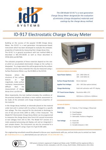
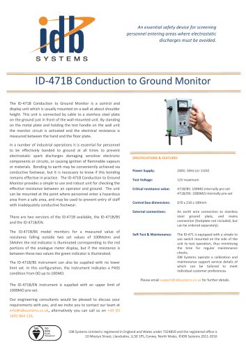
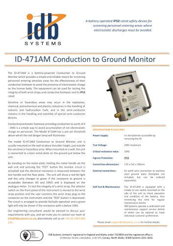
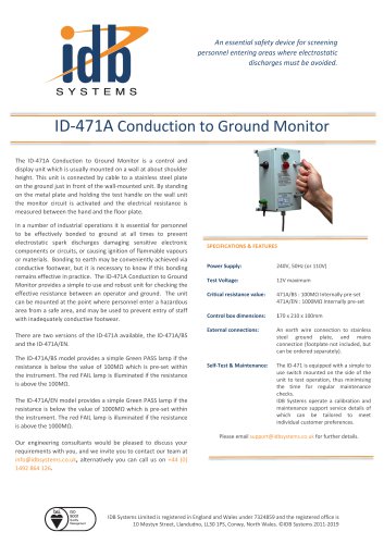
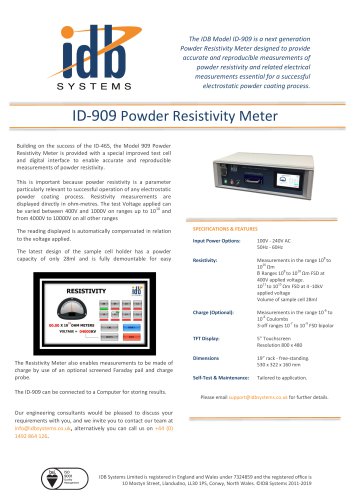
The IDB Model ID-917 is a next generation Charge Decay Meter designed for the evaluation of antistatic (charge dissipative) materials and coatings by the charge decay method. ID-917 Electrostatic Charge Decay Meter Building on the success of the popular ID-489 Charge decay Meter, the ID-917 is a next generation microprocessor-based instrument which has been developed to evaluate the antistatic properties of materials by measuring their charge decay time. The ID-917 is in general accordance with test method 4046 as described in MIL-STD-3010C as well as those described in IST40.2(01) and BS7506. The antistatic properties of these materials depend on the rate at which an accumulated electrostatic charge on the surface is dissipated. To a large extent this will be governed by the surface resistance and for many materials this may be measured using a Surface Resistance Meter, e.g. the ID-482A or the ID-914. SPECIFICATIONS & FEATURES Input Power Options: Charge Monitoring: Field-mill voltmeter with TFT display TFT Touch Screen Display: In the charge decay method, an electrode placed on the material under test and in contact with its surface is charged to a specific test voltage. The time required for the electrode to discharge to one of two pre-set limits (50% to 10%), is then measured. The Model 917 Electrostatic Charge Decay Meter can be programmed to measures the charge decay time from 0.01 second increments at test voltages from 1KV to 5KV. The Model 917 consists of a mains powered processing and display unit and an integrated 2part sample drawer. The instrument can also be connected to a desk-top or laptop PC using a Type A to Type B USB cable. Applied Test Voltage: More importantly, this test method simulates the conditions of the practical situation and allows a more realistic assessment to be made of the antistatic and charge dissipative properties of the material. Surface Charge Electrode: However, where the structure of the surface, texture or high magnitude, make surface resistance measurements difficult then the measurement of charge decay time is preferred. X = Polarity, Y=Test Voltage, Z=Reserved 0 = Fixed Negative 1 = Fixed Positive 2 = Selectable, Positive or Negative Test Voltage 0 = Fixed 1KV 1 = Fixed 5KV 2 = Variable between 1-5KV Our engineering consultants would be pleased to discuss your requirements with you, and we invite you to contact our team at [email protected], alternatively you can call us on +44 (0) 1492 864 126. IDB Systems Limited is registered in England and Wales under 7324859 and the registered office is 10 Mostyn Street, Llandudno, LL30 1PS, Conwy, North Wales. ©IDB Systems 2011-2016
Open the catalog to page 1All IDB Systems Ltd catalogs and technical brochures


- Measuring device
- Industrial tester
- Digital gauge
- Industrial measuring module
- Benchtop measuring module
- Measuring instrument with display
- Digital test equipment
- Laboratory measuring instrument
- High-precision gauge
- Field measuring instrument
- Control measuring instrument
- Process measuring module
- Hand-held gauge
- Electrical resistance test kit
- Ground bond tester
- Resistivity measuring instrument
- Powdery material measuring instrument
- Electrostatic field measuring instrument