iC227 Dual 11 GHz Sampling Oscilloscope
1 /22Pages

iC227 Dual 11 GHz Sampling Oscilloscope
1 /22Pages
Catalog excerpts

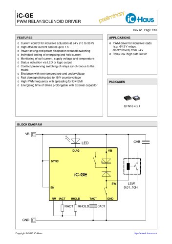
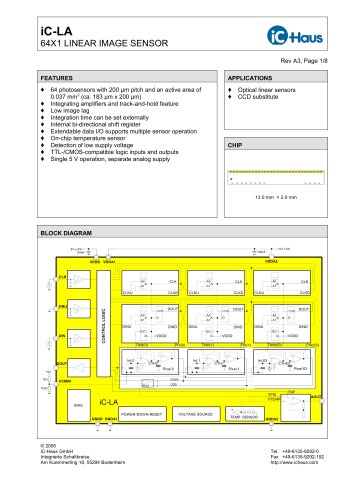
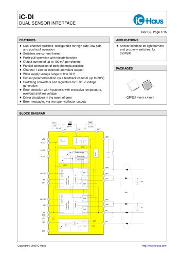
DUAL 11 GHz SAMPLING OSCILLOSCOPE Rev B1, Page 1/22 FEATURES o High-Speed Sampling Oscilloscope for periodic signals Dual 11 GHz DC coupled inputs 50 Ω inputs Optically isolated full speed USB interface Intuitive graphical PC software interface Low cost BLOCK DIAGRAM
Open the catalog to page 1
DUAL 11 GHz SAMPLING OSCILLOSCOPE Rev B1, Page 2/22 DESCRIPTION The iC227 is an 11 GHz bandwidth Sequential Sampling Oscilloscope. The 4 SMA inputs and 2 SMA outputs all have 50 Ω impedance and are DC coupled. The small, portable hardware package connects to a PC via an optically isolated full speed USB interface for PC protection and eliminates effects of noise from the USB bus and PC ground. All device control and monitoring is managed via an intuitive graphical PC software interface. The use of small package high speed ECL components allows extremely wide bandwidth and highly accurate self...
Open the catalog to page 2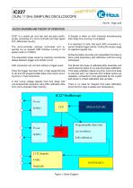
DUAL 11 GHz SAMPLING OSCILLOSCOPE Rev B1, Page 3/22 BLOCK DIAGRAM AND THEORY OF OPERATION iC227 is a simple yet very fast and accurate oscilloscope, consisting of a micro-controller and high speed ECL differential circuitry. The micro-controller receives commands and responds via an isolated USB interface running in full speed mode at 12 Mbit/s. The sequential scope works by inserting incremental delays between trigger and sample circuit. ADC conversion can not start without a trigger event. Once the trigger has been red, a high-speed ip op is set and the programmable delay lines starts counting...
Open the catalog to page 3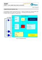
DUAL 11 GHz SAMPLING OSCILLOSCOPE Rev B1, Page 4/22 CONNECTION BLOCK DIAGRAM 11 GHz If full bandwidth is required, the input signal must be connected directly to CH1 and/or CH2. In this case the trigger needs to be supplied via a separate cable directly to the trigger input. The power splitter output must always be terminated with 50 Ohm. Figure 2: Full Bandwidth Setup
Open the catalog to page 4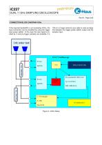
DUAL 11 GHz SAMPLING OSCILLOSCOPE Rev B1, Page 5/22 CONNECTION BLOCK DIAGRAM 4 GHz If the required bandwidth is not exceeding 4 GHz, the input connection can be simplied by using the trigger input power splitter. In this case the input signal is divided by 2 and pre-trigger samples are available, if a 150 cm or longer external coax cable is used as delay line between the trigger power splitter output and the sampler input.
Open the catalog to page 5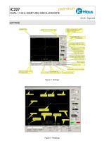
Keep left for fast rise time signals Adjust to right for slow ones, Jseful forfast trigger fin Compensate for 6dB loss if signal goes via trigger input power splitter. JCH1 display position relative Check to enable delay chan via slider in Hor. Position mode
Open the catalog to page 6
DUAL 11 GHz SAMPLING OSCILLOSCOPE Rev B1, Page 7/22 Source: TRIG1, TRIG2 Edge: Positive, Negative Trigger Position: -2048 mV ... +2048 mV (Input Via Trigger unchecked) Display Trace: checked, unchecked Vertical Resolution: 1V, 0.5V, 0.2V, 100mV, 50mV, 20mV, 10mV Input Via Trigger: checked, unchecked Position: full vertical screen Figure 7: Vertical Figure 8: Horizontal RUN, STOP button Status: Running, Waiting For TRIGGER, Stopped Figure 9: Status Snapshot button Options: Draw Dot, Grid On, Persistence, Filter AVG
Open the catalog to page 7
DUAL 11 GHz SAMPLING OSCILLOSCOPE Rev B1, Page 8/22 Display Measurement Annotation Figure 11: Measurement 3 types of measurement at a time, 15 different types of measurement in total Vmax : max. spike value Vmin : min. spike value Vpp : peak to peak amplitude value Vampl+ : max. amplitude ignoring spikes Vampl- : min. amplitude ignoring spikes VRMS : root mean square value VMEAN : mean value tRise : rise time tFall : fall time tPuls+ : positive pulse width tPuls- : negative pulse width 3 types of measurement for CH1 and CH2 --- : no measurement possible * : annotation button checked for this...
Open the catalog to page 8
DUAL 11 GHz SAMPLING OSCILLOSCOPE Rev B1, Page 9/22 Cursor CH2 Horizontal active Cursor 1 button unhidden Cursor 2 button unhidden and active Figure 16: Adjust cursor on Menu - Options - Settings Figure 17: Options settings Display: Snapshot Path Persistence Time 1...9 overlays Colors: CH1/CH2 (tting to cable colors) Autoupdate checkbox: live change of color settings
Open the catalog to page 9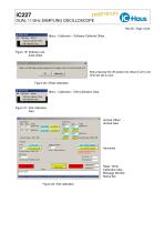
File | Calibration Options Software Calibrate Offset Edit Calibration Data Make sure that trigger signal is present and Sampler inputs are disconnected or OV Calibration Options Software Calibrate Offset Edit Calibration Data Vertical Offset- ISS51 Cal. time base scale I ■Vertical Gain- Cal. Time Base Linearity I Linearity Calibration will take Read complete
Open the catalog to page 10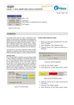
DUAL 11 GHz SAMPLING OSCILLOSCOPE Rev B1, Page 11/22 Menu - File: Load Setup Save Setup to a simple text le e.g. cong.txt Exit Program Figure 23: File menu CALIBRATION The scope iC227 does not have a certicate of calibration, but this device has software and hardware designed for auto time base calibration and calibration of vertical gains and offsets on both channels. There is also a software feature which allows manual calibration of the time base in case that the accuracy of the internal crystal and auto calibration are not sufcient. If the device is to be used in production where certied...
Open the catalog to page 11
DUAL 11 GHz SAMPLING OSCILLOSCOPE Rev B1, Page 12/22 Vertical gain The ”Vertical Gain” calibration process allows writing 4 gain calibration variables to the device ash memory. The Vpp measurement utility is used to acquire the correct gain setting. 4. Press the ”Cal. GL1” button 5. Press ”Write Cal. to iC227 ash memory” button Figure 29: Write calibration data 6. Press the scale @50 mV/div ”Set for Cal” button and follow the instructions. Figure 27: Vertical gain Vertical gain calibration steps 1. Make sure that scope was powered on for minimum 10 minutes 2. Open Calibration - Edit Calibration...
Open the catalog to page 12
DUAL 11 GHz SAMPLING OSCILLOSCOPE Rev B1, Page 13/22 Time base scale calibration steps Time base linearity calibration steps 1. Make sure that scope was powered on for minimum 10 minutes 2. Open Calibration - Edit Calibration Data 3. Press the ”Set for Cal GL” button and follow the instructions 1. Make sure that scope was powered on for minimum 10 minutes 2. Open Calibration - Edit Calibration Data Figure 34: Time base calibration Figure 32: Time base calibration 4. Press the ”Cal. Time base scale” button 5. Press ”Write Cal. To iC227 ash memory” button 3. Press the ”Set for Linearity Calibration”...
Open the catalog to page 13All IC-Haus catalogs and technical brochures
 Product Line Card
6 Pages
 iC-TL46 BLCC SD1C Blue LED
7 Pages
 iC212 HIGHSPEED PHOTORECEIVER
16 Pages
 Product overview
6 Pages


Archived catalogs
 iC-OV 5-Bit Optical Encoder
9 Pages
 Laser Webinar Handout
14 Pages
- Angular encoder
- Proximity switch
- Absolute rotary encoder
- Position transducer
- Multipole switch
- Transceiver module
- Optical rotary encoder
- Photoelectric sensor
- Linear position transmitter
- Magnetic rotary encoder
- Rectangular photoelectric sensor
- Flow sensor
- Linear encoder
- Touch switch
- Volume flow sensor
- Signal conditioner
- Magnetic position sensor
- Magnetic proximity sensor
- Metal position sensor
- Remote control receiver