iC212 HIGHSPEED PHOTORECEIVER
1 /16Pages

iC212 HIGHSPEED PHOTORECEIVER
1 /16Pages
Catalog excerpts

iC212 HIGHSPEED PHOTORECEIVER Rev B1, Page 1/16 FEATURES • • • • • • • • Bandwidth DC to 1.4 GHz Si PIN photodiode, Ø 0.2 mm for "No Slow Tail" (NST) option InGaAs photodiode, Ø 0.1 mm for "Near Infrared" (NIR) option Spectral response range λ = 320 to 1000 nm (NST) Spectral response range λ = 800 to 1800 nm (NIR) Amplifier transimpedance (gain) 3.125 V/mA Max. conversion gain 1.25 V/mW @ 700 nm (NST) Max. conversion gain 3.25 V/mW @ 1500 nm (NIR) APPLICATIONS • Fast pulse and transient measurement • Optical front-end for oscilloscopes
Open the catalog to page 1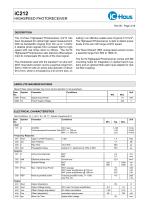
iC212 HIGHSPEED PHOTORECEIVER Rev B1, Page 2/16 DESCRIPTION The iC-Haus Highspeed Photoreceiver iC212 has been developed for optical high speed measurement. With its bandwidth ranging from DC up to 1.4 GHz it detects photo signals from constant light to high speed with rise times down to 200 ps. The iC212 Highspeed Photoreceiver also features offset adjustment to compensate DC levels of the input signal. The photodiode used with the standard "no slow tail" (NST, blue label) version covers a spectral range from 320 to 1000 nm with an active area diameter of about Ø 0.2 mm, which is increased by...
Open the catalog to page 2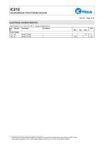
iC212 HIGHSPEED PHOTORECEIVER Rev B1, Page 3/16 ELECTRICAL CHARACTERISTICS Test Conditions: Vs = ±15 V, Ta = 25 °C∗ , System Impedace 50 Ω Item No. Supply Voltage Supply Current Caution! Even during regular operation, the aluminum case of the photoreceiver may heat up to 40 °C max. The output is clipped to -0.5 V, if the offset voltage is less than 0.5 V and no DC light is present.
Open the catalog to page 3
iC212 HIGHSPEED PHOTORECEIVER Rev B1, Page 4/16 CONTENTS The purchased parts package includes • Highspeed Photoreceiver iC212 (picture shows standard NST option) • Power adapter (230 VAC) • Coaxial cable with SMA plugs • SMA to BNC adapter • Fiber adapter
Open the catalog to page 4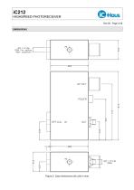
HIGHSPEED PHOTORECEIVER fiber adaption) Figure 2: Case dimensions (all units in mm)
Open the catalog to page 5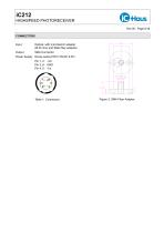
HIGHSPEED PHOTORECEIVER Input Optical, with microbench adapter Power Supply Hirose series HR10-7R-6P, 6-Pin
Open the catalog to page 6
HIGHSPEED PHOTORECEIVER Standard "No Slow Tail" (NST) option Figure 4: Spectral response (NST) Figure 5: Pulse response (NST)
Open the catalog to page 7
HIGHSPEED PHOTORECEIVER "Near Infrared" (NIR) option Figure 6: Spectral response (NIR) APPLICATION NOTES These application notes are meant to demonstrate some typical measurement tasks, carried out with the iC212 and verified with a standard optical power meter. Mesurement of total optical output power Popt 1. Put laser in pulse mode Figure 7: The laser light focused with a collecting lens onto the sensor 2. Adjust lens, for maximum amplitude at the output Figure 8: Oscilloscope reading Calculation: A= 635 nm, spectral response taken
Open the catalog to page 8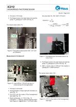
iC212 HIGHSPEED PHOTORECEIVER Rev B1, Page 9/16 4. Put laser in CW mode 5. Put Newport sensor into laser beam and read the power: Popt (Newport) = 0.641 mW (Fig. 9) The results match within 7%. tive area (Item No. 302: Aeff = 0.75 mm2 ) E(iC212) = = Figure 9: Total optical output power with 1 cm2 sensor (Newport) Measurement of Irradiance E Figure 11: Homogeneously illuminated area of ca. 4 cm x 4 cm 5. Put Newport sensor into laser beam and read the power: Popt (Newport) = 6.441 mW (Fig. 14) 6. With a sensor area of 100 mm2 this results in E(Newport) = 0.0644 mW/mm2 The results match within...
Open the catalog to page 9
HIGHSPEED PHOTORECEIVER Figure 13: Oscilloscope reading Figure 14: Newport sensor in the center of the ho- mogenised laser light Measuring time of flight Figure 15: Laser, pole filter, beam expander, beam Figure 17: One iC212 positioned 30 cm closer to Figure 16: No propagation time difference at same distance from beam splitter Figure 18: 30 cm distance difference means 1 ns propagation time difference
Open the catalog to page 10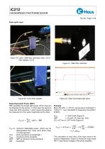
iC212 HIGHSPEED PHOTORECEIVER Rev B1, Page 11/16 Fiber-optic input Figure 19: Laser, SMA fiber collimator, fiber, iC212 fiber adapter, iC212 Figure 21: SMA fiber collimator Figure 20: iC212 fiber adapter Figure 22: Fiber transmitted light pulse Noise Equivalent Power (NEP) NEP specifies the lowest light power (Pmin) that can be detected by the sensor. In that case the signal to noise ratio (S/N) would be 1, which means the signal to be measured is of the same magnitude as the noise. Example Blue LED with λ = 473 nm, square wave modulated f = 1 MHz (T = 1 µs), bandwidth of measuring circuit BW...
Open the catalog to page 11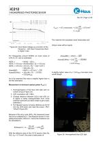
iC212 HIGHSPEED PHOTORECEIVER Rev B1, Page 12/16 This matches the calculated value reasonably well. Figure 23: Input Noise Voltage as a function of the frequency - with lower frequencies there is higher noise For frequencies around 93 MHz an input noise of √ 215 nV/ Hz can be estimated. NEP(λ) = INV(f) * 1/S(λ) NEP(λ = 473 nm) = INV(93 MHz) / S(λ = 473 nm) √ NEP(λ = 473 nm) = 215 nV/ √ * 1 mW / 0.67 V Hz = 320 pW/ Hz √ Noise(BW) = NEP(λ =√ nm) * BW 473 √ Noise(93 MHz) = 320 pW/ Hz * 93 MHz = 3.09 µWRMS Output noise without signal: √ Noise(BW ) = INV(f ) ∗ BW √ nV Noise(93 MHz) = 215 √ ∗ 93 MHz...
Open the catalog to page 12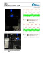
HIGHSPEED PHOTORECEIVER Figure 25: Homogeniously illuminated iC212 Figure 28: Noise with signal barely detectable Figure 26: Homogeniously illuminated Newport
Open the catalog to page 13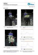
HIGHSPEED PHOTORECEIVER Ulbricht sphere Figure 29: 3-port Ulbricht sphere with iC212 and Newport power meter Figure 31: Laser light coupled into the Ulbricht Figure 32: Laser pulse with 260 ps rise time (chan- Figure 30: HG1M laser controller with 2 W CW laser diode On the ideal size of an Ulbricht sphere see also "How to select an integrating sphere for your application" by Valerie C. Coffey at www.laserfocusworld.com. Figure 33: Due to size of Ulbricht sphere the pulse gets distorted (ca. 4 ns rise time)
Open the catalog to page 14
iC212 HIGHSPEED PHOTORECEIVER Rev B1, Page 15/16 Equipment used Mesuring instruments Tektronix: TDS7404B, 4 GHz, 20 GS/s, 4-Channel Digital Phosphor Oscilloscope Newport: Optical Power Meter Model 840 Newport: Sensor 818-ST, Sensor 818-UV, Sensor 818-ST/CM 819D-SL-3.3, 3-Port 3.3" Spectralon Newport: Ulbricht Sphere Ocean Optics: USB2000 Fiber-optic Spectrometer 320 - 1100 nm Omicron: LDM639.40.500, 40 mW Laser, fMOD > 500 MHz Femto: HSA-X-S-1G4-SI, Ultra High Speed Photoreceiver iC-Haus: iC212 Highspeed Photoreceiver, DC to 1.4 GHz iC-Haus: iC227, Dual Channel 11GHz Sequential Sampling Oscilloscope...
Open the catalog to page 15All IC-Haus catalogs and technical brochures
 Product Line Card
6 Pages
 iC-TL46 BLCC SD1C Blue LED
7 Pages
 Product overview
6 Pages


Archived catalogs
 iC-OV 5-Bit Optical Encoder
9 Pages
 Laser Webinar Handout
14 Pages
- Angular encoder
- Proximity switch
- Absolute rotary encoder
- Position transducer
- Multipole switch
- Transceiver module
- Optical rotary encoder
- Photoelectric sensor
- Linear position transmitter
- Magnetic rotary encoder
- Rectangular photoelectric sensor
- Flow sensor
- Linear encoder
- Touch switch
- Volume flow sensor
- Signal conditioner
- Magnetic position sensor
- Magnetic proximity sensor
- Metal position sensor
- Remote control receiver