iC-JE Power-Saving PWM Relay/Solenoid Driver
1 /9Pages

iC-JE Power-Saving PWM Relay/Solenoid Driver
1 /9Pages
Catalog excerpts

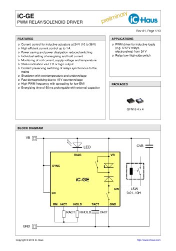
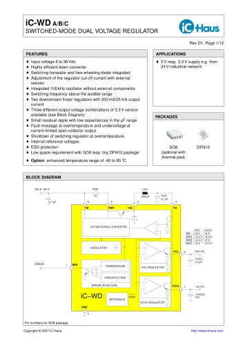
iC-JE PWM RELAY/SOLENOID DRIVER Rev F1, Page 1/9 FEATURES o Wide operating voltage range of 10 to 45 Vdc o PWM control for coil currents of 40 to 300 mA o Coil current for energise and hold modes set by an external resistor o Coil current monitored during energise mode, detection of load breakage and voltage errors o Automatic current reduction after 100 ms to reduce the power consumption in hold mode o The internal free-wheeling alteration function supports PWM operation and quick demagnetising during shutdown o Status signalled at the current-limited LED output o Shutdown with excessive temperature and low voltage o Integrated oscillator needs no external components o PWM frequency is beyond audible range o Protective circuitry against damage by ESD o Minimum space requirements, few external components o PWM drive for inductive loads (e.g. relays, electrovalves) o Relay low-/high-side switch TURN−ON CURRENT LOW VOLTAGE THERMAL SHUTDOWN HOLD MODE DELAY DRIVER OUTPUT TURN−ON RESET
Open the catalog to page 1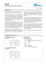
iC-JE PWM RELAY/SOLENOID DRIVER Rev F1, Page 2/9 DESCRIPTION iC-JE is a PWM driver for inductive loads, such as relay coils, solenoid valves and small DC motors. The setpoint for the coil current is preset with the help of the RSET external resistor. 60 to 300 mA can be set for energise mode which then automatically drop to 2/3 of this value (40 to 200 mA) during hold mode. The device is switched to hold mode after 100 ms provided that the set coil current is obtained during energising (PWMOK = 1). The changeover between energise and hold modes is suitable for typical relay drives which require...
Open the catalog to page 2
iC-JE PWM RELAY/SOLENOID DRIVER Rev F1, Page 3/9 ABSOLUTE MAXIMUM RATINGS Beyond these values damage may occur; device operation is not guaranteed. Item No. Junction Temperature Storage Temperature THERMAL DATA Operating Conditions: VB = 10...45 V, LOUT = 0.01...10 H, RSET = 10...60 kΩ Item No. Operating Ambient Temperature Range Thermal Resistance Chip/Ambient Thermal Resistance Chip/Ambient All voltages are referenced to ground unless otherwise stated. All currents into the device pins are positive; all currents out of the device pins are negative.
Open the catalog to page 3
iC-JE PWM RELAY/SOLENOID DRIVER Rev F1, Page 4/9 ELECTRICAL CHARACTERISTICS Operating Conditions: VB = 10...45 V, LOUT = 0.01...10 H, RSET = 10...60 kΩ, Tj = -25...125 °C, unless otherwise noted. LED connected or pin LED linked to GND (via ca. 500 Ω resistor or capacitor). Item No. Permissible Supply Voltage Range Clamp Voltage lo at all Pins I() = -4 mA, other Pins open Clamp Voltage hi at VB, IN, ISET I() = 4 mA, other Pins open I(OUT) = 4 mA, other Pins open Vc()hi = V(LED) − V(VB); I(LED) = 4 mA, other Pins open Permissible Energising Current Increased Energising Current by RC-circuit at...
Open the catalog to page 4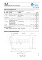
iC-JE PWM RELAY/SOLENOID DRIVER Rev F1, Page 5/9 ELECTRICAL CHARACTERISTICS Operating Conditions: VB = 10...45 V, LOUT = 0.01...10 H, RSET = 10...60 kΩ, Tj = -25...125 °C, unless otherwise noted. LED connected or pin LED linked to GND (via ca. 500 Ω resistor or capacitor). Item No. Thermal Lock-on Threshold Decreasing temperature Thermal Shutdown Hysteresis Flash Frequency on Error Reference Voltage Short-Circuit Current Transfer Value for Energising I(OUT)start = 60...300 mA Current RSET = K1 / I(OUT)start Relative Current Ratio It(OUT)hold / It(OUT)start (Trigger Thresholds Ratio: Hold vs....
Open the catalog to page 5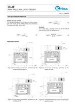
iC-JE PWM RELAY/SOLENOID DRIVER Rev F1, Page 6/9 APPLICATIONS INFORMATION Setting the coil current The following equations can be given for the energise and hold modes of the PWM control using Electrical Characteristics Nos. 403 to 408: Example For a relay with a starting current of 100 mA (66 mA hold current) RSET is calculated as: CONTROL ISET Figure 2: Driver/relay combination activated via the external control input IN Figure 3: Driver/relay combination activated via the supply pin GND 10...45 V CONTROL ISET RSET 10...60 kΩ Figure 4: Driver/relay combination activated via the supply pin VB...
Open the catalog to page 6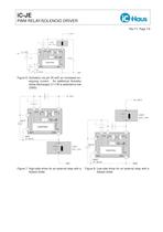
iC-JE PWM RELAY/SOLENOID DRIVER Rev F1, Page 7/9 10...45 V Figure 6: Activation via pin IN with an increased energizing current. An additional Schottky diode discharges C1 if IN is switched to low (GND) 10...45 V CONTROL ISET iC−JE CONTROL ISET Figure 7: High-side driver for an external relay with a yback diode Figure 8: Low-side driver for an external relay with a yback diode
Open the catalog to page 7
iC-JE PWM RELAY/SOLENOID DRIVER Rev F1, Page 8/9 EVALUATION BOARD The iC-JE is equipped with a Evaluation Board for test purposes. The following gures show the circuit diagram as well as the top and bottom layout of the test PCB. Evaluation Circuit Application Field The board comes with a strap between IN and SENSE1 (application equal to Fig. 4). The actual coil current can be measured by the voltage drop between SENSE1 and SENSE2 (1 mV/mA). Figure 9: Schematic diagram of the Evaluation Board I(LOUT) Figure 11: Oscilloscope graph of the evaluation circuit (sampled) Figure 10: Evaluation Board...
Open the catalog to page 8
iC-JE PWM RELAY/SOLENOID DRIVER Rev F1, Page 9/9 ORDERING INFORMATION Order Designation Evaluation Board For information about prices, terms of delivery, other packaging options etc. please contact: iC-Haus GmbH Am Kuemmerling 18 D-55294 Bodenheim GERMANY
Open the catalog to page 9All IC-Haus catalogs and technical brochures
 Product Line Card
6 Pages
 iC-TL46 BLCC SD1C Blue LED
7 Pages
 iC212 HIGHSPEED PHOTORECEIVER
16 Pages
 Product overview
6 Pages


Archived catalogs
 iC-OV 5-Bit Optical Encoder
9 Pages
 Laser Webinar Handout
14 Pages
- ERLO rotary encoder
- Proximity switch
- ERLO absolute rotary encoder
- ERLO position sensor
- Multipole switch
- Transceiver module
- ERLO optical rotary encoder
- Photoelectric sensor
- ERLO linear position sensor
- ERLO magnetic rotary encoder
- Rectangular photoelectric sensor
- Flow sensor
- Linear encoder
- Volume flow sensor
- Touch switch
- ERLO signal conditioner
- ERLO magnetic position sensor
- Magnetic proximity sensor
- ERLO metal position sensor
- Remote control receiver