iC-HD7 Quad Differential Line Driver, Pin-Compatible with xx7272 and 26LS31

iC-HD7 Quad Differential Line Driver, Pin-Compatible with xx7272 and 26LS31
Catalog excerpts

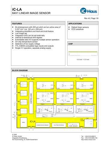
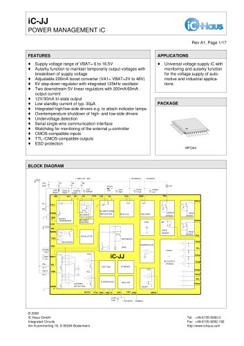
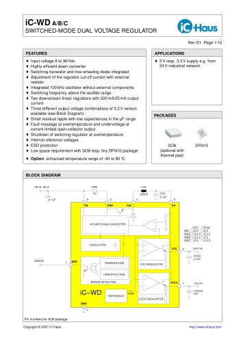
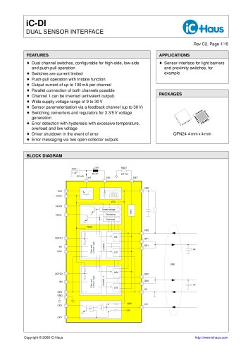
iC-HD7 QUAD DIFFERENTIAL LINE DRIVER Rev A5, Page 1/8 FEATURES ' Complementary short-circuit-proof push-pull driver stages for RS422 and 24 V applications up to 2MHz ' Pin-compatible to 26LS31, xx7272 ' Integrated line adaptation for high signal quality at 24V ' Moderate slew rate reduces EMI ' High driving capability of typically 200mA at 24V ' Output saturation of just 0.3 V at 40 mAdc ' Tristate function for bus applications with excessive temperature shutdown ' TTL-/CMOS-compatible Schmitt trigger inputs, voltage-proof to 40 V ' 4.5 to 35 V single supply operation with low static power dissipation ' Operating temperature from -25 to 125 °C (-40 °C is optional) APPLICATIONS ' Line drivers for 24 V control engineering ' Linear scales and encoders ' Sensor systems PACKAGES SO16N RoHS compliant BLOCK DIAGRAM VB O1 NO1 GND I1 DRIVER STAGES iC-HD7 O2 NO2 O3 NO3 O4 NO4 I2 I3 I4 NEN 4.5..35 V LINE PLC UNDERVOLTAGE & OVERTEMPERATURE Copyright © 2010 iC-Haus http://www.ichaus.com
Open the catalog to page 1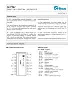
iC-HD7 QUAD DIFFERENTIAL LINE DRIVER Rev A5, Page 2/8 DESCRIPTION iC-HD7 is a robust line driver for industrial 5 V and 24 V applications with four complementary output channels. For signal lines with a characteristic impedance of 30 to 140 the integrated line adapter, optimized to 75 , minimizes ringing effects which arise when there is no line termination. At a supply of 24 V the push-pull driver stages typically provide 200mA to discharge the line and also have a low saturation voltage (of typically 200mV with a 40mA low-side load). The outputs are current limited and short-circuit-proof,...
Open the catalog to page 2
iC-HD7 QUAD DIFFERENTIAL LINE DRIVER Rev A5, Page 3/8 ABSOLUTE MAXIMUM RATINGS Beyond these values damage may occur; device operation is not guaranteed. Absolute Maximum Ratings are no Operating Conditions. Integrated circuits with system interfaces, e.g. via cable accessible pins (I/O pins, line drivers) are per principle endangered by injected interferences, which may compromise the function or durability. The robustness of the devices has to be verified by the user during system development with regards to applying standards and ensured where necessary by additional protective circuitry. By...
Open the catalog to page 3
iC-HD7 QUAD DIFFERENTIAL LINE DRIVER Rev A5, Page 4/8 ELECTRICAL CHARACTERISTICS Operating Conditions: VB = 4.5...35 V, Tj = -40...125 °C, unless otherwise noted Item Symbol Parameter Conditions Unit No. Min. Typ. Max. Total Device 001 VB Permissible Supply Voltage 4.5 35 V 002 I(VB) Supply Current in VB NEN= lo, outputs not loaded 3.8 5.5 mA 003 I(VB)tri Tristate Current Consumption in VB NEN= hi 2.7 mA 004 Vc()lo Clamp Voltage lo at NEN, Ix, NERR I() = -1mA -1.2 -0.3 V 005 Vc()hi Clamp Voltage hi at NEN, Ix, NERR I() = 1mA VB + 0.3 VB + 1.2 V 006 Vc()lo Clamp Voltage lo at O1..O4, NO1..NO4...
Open the catalog to page 4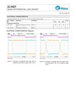
iC-HD7 QUAD DIFFERENTIAL LINE DRIVER Rev A5, Page 5/8 ELECTRICAL CHARACTERISTICS Operating Conditions: VB = 4.5...35 V, Tj = -40...125 °C, unless otherwise noted Item Symbol Parameter Conditions Unit No. Min. Typ. Max. Temperature Monitoring 601 Toff Shutdown Temperature Threshold NEN= lo 130 150 170 °C 602 Toff Temperature Hysteresis NEN= lo 8 °C ELECTRICAL CHARACTERISTICS: Diagrams Figure 1: Example of moderate slew rate with unloadad Ox and NOx outputs (VB = 24 V) Figure 2: Example of typical line end signal without termination (VB = 24V, length of cable 10 m)
Open the catalog to page 5
iC-HD7 QUAD DIFFERENTIAL LINE DRIVER Rev A5, Page 6/8 APPLICATION NOTE Reverse polarity and circuit protection For reverse polarity protection electronic circuitry are usually powered via a diode D in the supply line. Under normal operating conditions, this diode will not affect function of the circuitry when the additional forward voltage drop across the diode is accounted for operating voltage specification. If the supply voltage Vsupply is suddenly reversed, a load capacitor C may be still fully charged. Therefore, the diode D has to be selected to withstand a voltage difference of at least...
Open the catalog to page 6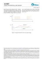
iC-HD7 QUAD DIFFERENTIAL LINE DRIVER Rev A5, Page 7/8 diode ZD should draw substantial current. Therefore, their breakdown voltage should be chosen to be some volts higher. A 36 V rated suppressor diode with 1.5kW pulse power capability like a 1N6284 or 1.5KE36 the minimum breakdown voltage measured at a test current of 1mA is stated as 32.4V. Also, a zener diode like a BZT03C36 rated for 36V also shows a minimum breakdown voltage of 32.4 V, but measured at test current of 10 mA. Figure 4: Using zener diode ZD to limit circuit supply voltage iC-Haus expressly reserves the right to change its...
Open the catalog to page 7
iC-HD7 QUAD DIFFERENTIAL LINE DRIVER Rev A5, Page 8/8 ORDERING INFORMATION Type Package Order Designation iC-HD7 SO16N iC-HD7 SO16N For technical support, information about prices and terms of delivery please contact: iC-Haus GmbH Tel.: +49 (61 35) 92 92-0 Am Kuemmerling 18 Fax: +49 (61 35) 92 92-192 D-55294 Bodenheim Web: http://www.ichaus.com GERMANY E-Mail: [email protected] Appointed local distributors: http://www.ichaus.com/sales_partners
Open the catalog to page 8All IC-Haus catalogs and technical brochures
 Product Line Card
6 Pages
 iC-TL46 BLCC SD1C Blue LED
7 Pages
 iC212 HIGHSPEED PHOTORECEIVER
16 Pages
 Product overview
6 Pages


Archived catalogs
 iC-OV 5-Bit Optical Encoder
9 Pages
 Laser Webinar Handout
14 Pages
- Angular encoder
- Proximity switch
- Absolute rotary encoder
- Position transducer
- Multipole switch
- Transceiver module
- Optical rotary encoder
- Photoelectric sensor
- Linear position transmitter
- Magnetic rotary encoder
- Rectangular photoelectric sensor
- Flow sensor
- Linear encoder
- Touch switch
- Volume flow sensor
- Signal conditioner
- Magnetic position sensor
- Magnetic proximity sensor
- Metal position sensor
- Remote control receiver