iC-GE PWM Relay/Solenoid Driver for a Wide Operating Voltage Range (1 A)
1 /13Pages

iC-GE PWM Relay/Solenoid Driver for a Wide Operating Voltage Range (1 A)
1 /13Pages
Catalog excerpts
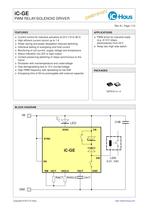
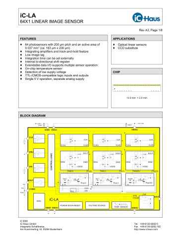
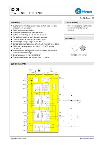
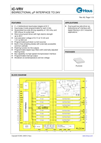
iC-GE PWM RELAY/SOLENOID DRIVER o PWM driver for inductive loads (e.g. 6/12 V relays, electrovalves) from 24 V o Relay low-/high-side switch Current control for inductive actuators at 24 V (10 to 36 V) High efcient current control up to 1 A Power saving and power dissipation reduced switching Individual setting of energising and hold current Monitoring of coil current, supply voltage and temperature Status indication via LED or logic output Contact preserving switching of relays synchronous to the mains Shutdown with overtemperature and undervoltage Fast demagnetising due to 15 V countervoltage High PWM frequency with spreading for low EMI Energising time of 50 ms prolongable with external capacitor BLOCK DIAGRAM
Open the catalog to page 1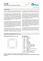
iC-GE PWM RELAY/SOLENOID DRIVER Rev A1, Page 2/13 DESCRIPTION iC-GE is a PWM driver for inductive loads, such as relay coils, solenoid valves and other inductive loads. is provided by the internal oscillator. Varying this frequency between 70 kHz and 90 kHz reduces the EMI. The setpoints for the coil’s energising and hold current are preset by means of external resistors RACT and RHOLD. These currents can be set in a range from 100 mA to 1 A. The iC-GE intrinsically switches from energising to hold mode after 50 ms provided that the set energising current has been reached. A capacitor at TACT...
Open the catalog to page 2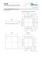
iC-GE PWM RELAY/SOLENOID DRIVER y inar im prel Rev A1, Page 3/13 PACKAGE DIMENSIONS QFN16 4 mm x 4 mm All dimensions given in mm.
Open the catalog to page 3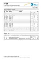
iC-GE PWM RELAY/SOLENOID DRIVER y inar im prel Rev A1, Page 4/13 ABSOLUTE MAXIMUM RATINGS Beyond these values damage may occur; device operation is not guaranteed. Item No. Junction Temperature Storage Temperature THERMAL DATA Operating Conditions: VB = 10...36 V, LSW = 0.01...10 H, RACT = 5...50 kΩ, RHOLD = 5...50 kΩ Item No. T01 T02 Operating Ambient Temperature Range Thermal Resistance Chip/Ambient -40 Mounted to a PCB, therm. PAD at ca. 2 cm² copper area All voltages are referenced to ground unless otherwise stated. All currents owing into the device pins are positive; all currents owing...
Open the catalog to page 4
iC-GE PWM RELAY/SOLENOID DRIVER y inar im prel Rev A1, Page 5/13 ELECTRICAL CHARACTERISTICS Operating Conditions: VB = 10...36 V, LSW = 0.01...10 H, RACT = 5...50 kΩ, RHOLD = 5...50 kΩ, Tj = -40...125 °C. Item No. Permissible Supply Voltage Range Clamp Voltage lo at all Pins except SYNC I() = -4 mA, other Pins open Clamp Voltage lo an SYNC I() = -4 mA, andere Pins offen Clamp Voltage hi at VB, EN, DIAG, SYNC I() = 4 mA, other Pins open Clamp Voltage hi at IACT, IHOLD, I() = 4 mA, other pins open TACT I(OUT) = 4 mA, other Pins open PWM-Current Range Short-circuit Current Clamp Voltage hi at PWM-FreeWheeling...
Open the catalog to page 5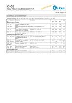
iC-GE PWM RELAY/SOLENOID DRIVER y inar im prel Rev A1, Page 6/13 ELECTRICAL CHARACTERISTICS Operating Conditions: VB = 10...36 V, LSW = 0.01...10 H, RACT = 5...50 kΩ, RHOLD = 5...50 kΩ, Tj = -40...125 °C. Item No. Reference IACT and IHOLD 701 Reference Voltage at IACT and IHOLD Short-Circuit Current in IACT and V(ISET) = 0 V or V(IHOLD) = 0 V IHOLD Transfer Value for Energising Current RACT = K1 / I(SW)act Transfer Value for Hold Current RHOLD = K2 / I(SW)hold Energising Time Prolongation TACT C01 tpPWMlo Propagation Delay from EN = hi to changeover from IACT to IHOLD TACT not connected (ssee...
Open the catalog to page 6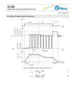
iC-GE PWM RELAY/SOLENOID DRIVER y inar im prel Rev A1, Page 7/13 ELECTRICAL CHARACTERISTICS: Diagrams Figure 1: Operation modes energise, hold, turn-off tmag ≈
Open the catalog to page 7
iC-GE PWM RELAY/SOLENOID DRIVER Rev A1, Page 8/13 APPLICATIONS INFORMATION Setting the coil current The following equations can be given for the energise and hold modes of the PWM control using Electrical Characteristics Nos. 703 resp. 704: Example For a relay with a starting current of 200 mA and 100 mA hold current the following applies: Figure 2: Activation by switching VB RACT = 5 kΩ for 1 A energising current and RHOLD = 10 kΩ for 500 mA hold current Figure 3: Activation by switching GND DIAG DIAG Figure 4: Activation via EN feedback from DIAG with 5 V logic levels Figure 5: 470 nF for 470...
Open the catalog to page 8
iC-GE PWM RELAY/SOLENOID DRIVER Figure 6: High-side driver for relays with freewheeling diode Figure 7: Low-side driver for relays with free-wheeling diode The benet from synchronous switching may be utilised, if the switching times are short and reproducible. Figure 8: Utilising the SYNC input V(SYNC) By means of resistors RS* and capacitors CS* a phase shifted signal at SYNC is derived from the 50 Hz load supply. Thus the relay is activated resp. deactivated with zero crossing of the load supply after working EN. The phase shift is used to compensate the switching delay of the relay so that...
Open the catalog to page 9
iC-GE PWM RELAY/SOLENOID DRIVER y inar im prel Rev A1, Page 10/13 Application example with four relays of equal acceleration REL# N d VBLn VBLmin VBLmax ISWn Ri Rimax PvLn Relay type No. of turns Wire diameter Nominal coil supply voltage Minimum required supply voltage 75% of VBLn Maximum allowed supply voltage VBLn + 25% Nominal coil current Coil resistance at room temperature Elevated coil resistance at 80 °C Power dissipation in the coil VBLn2 / Ri Table 4: Manufacturer data Imin Energising current VBLmin / RImax, for sure switching of the realy at high temperature and low power supply RACT...
Open the catalog to page 10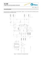
iC-GE PWM RELAY/SOLENOID DRIVER y inar im prel Rev A1, Page 11/13 EVALUATION BOARD iC-GE comes with an evaluation board for test purpose. Figures 11 and 12 show both the schematic and the component side of the evaluation board. Figure 11: Schematic of the evaluation board
Open the catalog to page 11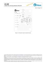
iC-GE PWM RELAY/SOLENOID DRIVER y inar im prel Rev A1, Page 12/13 Figure 12: Evaluation board (component side) iC-Haus expressly reserves the right to change its products and/or specications. An info letter gives details as to any amendments and additions made to the relevant current specications on our internet website www.ichaus.de/infoletter; this letter is generated automatically and shall be sent to registered users by email. Copying – even as an excerpt – is only permitted with iC-Haus’ approval in writing and precise reference to source. iC-Haus does not warrant the accuracy, completeness...
Open the catalog to page 12All IC-Haus catalogs and technical brochures
 Product Line Card
6 Pages
 iC-TL46 BLCC SD1C Blue LED
7 Pages
 iC212 HIGHSPEED PHOTORECEIVER
16 Pages
 Product overview
6 Pages


Archived catalogs
 iC-OV 5-Bit Optical Encoder
9 Pages
 Laser Webinar Handout
14 Pages