iC-DI Dual Sensor Interface with 3.3 V/5 V Power Supply
iC-DI Dual Sensor Interface with 3.3 V/5 V Power Supply
- Configurable dual channel switches for high-side, low-side, and push-pull operations with current limitation and short-circuit protection.
- Output current capability of up to 100 mA per channel, with options for parallel connection.
- Operates within a wide supply voltage range of 9 to 30 V.
- Error detection with hysteresis for temperature, overload, and low voltage, including driver shutdown in error conditions.
- Integrated switching converters and regulators for generating 3.3/5 V outputs.
- Used as a sensor interface for light barriers and proximity switches.
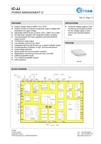
The iC-DI is a monolithic interface designed for driving digital sensors to peripheral devices like PLCs and relays. It supports multiple switch operations and includes error signaling via open-collector outputs. The device also features a feedback channel for sensor parameterization and integrated voltage generation for 5 V and 3.3 V outputs.
Packaged in a QFN24 4 mm x 4 mm, the device has specific pin functions for configuration, input, output, and error signaling. Pins GND and VN should not be externally connected to prevent high current flow under reverse bias conditions.
Defines the limits beyond which the device may be damaged, including maximum voltages and currents for various pins, with conditions for reverse bias and ESD susceptibility.
Operating conditions include a supply voltage range of 9 to 30 V and a junction temperature range of -40 to 125 °C. Thermal resistance from chip to ambient is specified for surface-mounted conditions.
Details on total device operation, low-side and high-side switches, short-circuit/overload monitoring, voltage monitoring, temperature monitoring, and input/output thresholds. Includes permissible supply voltages, current limits, saturation voltages, and propagation delays.
Nominal voltage at VH is between 6.4 to 7.7 V, with 70% efficiency for the VH-switching regulator. Details on cut-off currents, voltages, saturation voltages, and forward voltages of the fly-back diode are provided.
Nominal voltage at VCC is 4.75 to 5.25 V, requiring a 150 nF capacitor. Monitor thresholds and hysteresis for VCC and VCC3 are specified.
Oscillator frequency ranges from 1.2 to 2.75 MHz, with specific values at 27 °C. Voltage and current specifications for ISET are also provided.
Mechanisms for overload detection to protect against excessive power dissipation are described, including switch clocking during overloads and the role of an 8-bit counter.
Switch configuration is determined by pins QCFG1 and QCFG2, with specific voltage levels activating or deactivating high-side and low-side switches.
Function tables for channels 1 and 2, and the feedback channel, detailing the states of various pins and their corresponding outputs.
Illustrates recommended protective circuitry against reverse bias and transients, with suggested component values and configurations.
Includes a schematic and component side view of a demo board for testing purposes, along with ordering information for the iC-DI and evaluation board.
iC-Haus reserves the right to change specifications without notice and does not warrant the accuracy or completeness of the information provided.
Catalog excerpts

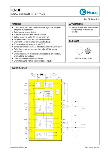
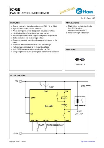
iC-DI DUAL SENSOR INTERFACE Rev C2, Page 1/15 FEATURES © Dual channel switches, configurable for high-side, low-side and push-pull operation © Switches are current limited © Push-pull operation with tristate function © Output current of up to 100mA per channel © Parallel connection of both channels possible © Channel 1 can be inverted (antivalent output) © Wide supply voltage range of 9 to 30 V © Sensor parameterisation via a feedback channel (up to 30 V) © Switching converters and regulators for 3.3/5 V voltage generation © Error detection with hysteresis with excessive temperature, overload and low voltage © Driver shutdown in the event of error © Error messaging via two open-collector outputs APPLICATIONS © Sensor interface for light barriers and proximity switches, for example PACKAGES QFN24 4mmx 4mm BLOCK DIAGRAM =1 BIAS Overload CHANN. 2 CHANN. 1 Overtemp. Undervoltage QN2 QP2 VCC VH VHL ISET CFP CFO QCFG2 INV1 IN1 QCFG1 VCC VCC3 NOVL GND IN2 NUVD OEN 1 nF CFI VN VBR VN QN1 QP1 VBO VCC3 HS1 LS1 LS2 HS2 22 uH LVH ..50 mA RSET 1 uF CVH LINE Filter and Control Logic Filter and Control Logic 8.2 kW VBR 1 nF Copyright © 2008 iC-Haus http://www.ichaus.com
Open the catalog to page 1
iC-DI DUAL SENSOR INTERFACE Rev C2, Page 2/15 DESCRIPTION iC-DI is a monolithic interface iC with two independent switching channels which enables digital sensors to drive peripheral elements, such as programmable logic controllers (PLC) and relays, for example. The switches can be operated as push-pull, highside or low-side switches using inputs QCFG1 and QCFG2 (open, high and low) and are enabled or disabled via input OEN. They are designed to cope with high driver currents of 100mA (RSET = 8.2 k ), are current limited and also short-circuit-proof in that they shut down should excessive temperature...
Open the catalog to page 2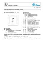
iC-DI DUAL SENSOR INTERFACE Rev C2, Page 3/15 PACKAGES QFN24 4mm x 4mm to JEDEC Standard PIN CONFIGURATION QFN24 4mm x 4mm 7 8 9 10 11 1 2 3 4 5 13 14 15 22 21 6 12 16 17 20 19 18 24 23 DI code... ... PIN FUNCTIONS No. Name Function 1 ISET Reference Current for current limitation of driver outputs 2 INV1 Inverting Input Channel 1 3 IN1 Input Channel 1 PIN FUNCTIONS No. Name Function 4 QCFG1 Configuration Input Channel 1 5 QCFG2 Configuration Input Channel 2 6 IN2 Input Channel 2 7 OEN Output Enable Input 8 NOVL Overload Error Output 9 NUVD Undervoltage Error Output 10 CFO Output Feedback Channel...
Open the catalog to page 3
iC-DI DUAL SENSOR INTERFACE Rev C2, Page 4/15 ABSOLUTE MAXIMUM RATINGS Beyond these values damage may occur; device operation is not guaranteed. Absolute Maximum Ratings are no Operating Conditions. Integrated circuits with system interfaces, e.g. via cable accessible pins (I/O pins, line drivers) are per principle endangered by injected interferences, which may compromise the function or durability. The robustness of the devices has to be verified by the user during system development with regards to applying standards and ensured where necessary by additional protective circuitry. By the manufacturer...
Open the catalog to page 4
iC-DI DUAL SENSOR INTERFACE Rev C2, Page 5/15 ABSOLUTE MAXIMUM RATINGS (cont’d) Item Symbol Parameter Conditions Unit No. Min. Max. G027 Ts Storage Temperature Range -40 150 °C THERMAL DATA Operating Conditions: VBO = 9...30 V, VBR = 9...30V (both referenced to VN), Tj = -40...125 °C, RSET = 8.2 k ±1%, unless otherwise stated Item Symbol Parameter Conditions Unit No. Min. Typ. Max. T01 Ta Operating Ambient Temperature Range (extended range on request) -40 85 °C T02 Rthja Thermal Resistance Chip/Ambient Surface mounted, thermal pad soldered to ca. 2 cm² heat sink 30 40 K/W All voltages are referenced...
Open the catalog to page 5
iC-DI DUAL SENSOR INTERFACE Rev C2, Page 6/15 ELECTRICAL CHARACTERISTICS Operating Conditions: VBO = 9...30 V, VBR = 9...30 V (both referenced to VN), Tj = -40...125 °C, RSET = 8.2 k ±1%, unless otherwise stated Item Symbol Parameter Conditions Unit No. Min. Typ. Max. Total Device 001 VBO Permissible Supply Voltage Referenced to VN 9 24 30 V 002 I(VBO) Supply Current in VBO No load, I(QP1) = I(QP2) = 0, HSx switched on 0.3 mA 003 VBR Permissible Supply Voltage 9 24 30 V 004 I(VBR) Supply Current in VBR VH connected to VBR, no load, I(VCC) = I(VCC3) = 0, V(OEN) = hi 6 mA 005 Vc()hi Clamp Voltage...
Open the catalog to page 6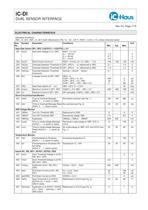
iC-DI DUAL SENSOR INTERFACE Rev C2, Page 7/15 ELECTRICAL CHARACTERISTICS Operating Conditions: VBO = 9...30 V, VBR = 9...30 V (both referenced to VN), Tj = -40...125 °C, RSET = 8.2 k ±1%, unless otherwise stated Item Symbol Parameter Conditions Unit No. Min. Typ. Max. High-Side Switch QP1, QP2; V(QCFG1) = V(QCFG2) = 5V 201 Vs()hi Saturation Voltage hi vs. VBO RSET = 5.1 k ; I() = -100mA -1.2 V I() = -50mA -0.7 V I() = -10mA -0.3 V 202 Isc()hi Short-Circuit Current hi RSET = 8.2 k , V() = 0...VBO - 1.5 V -160 -125 -100 mA 203 Vol()on Overload Detection Threshold on QP1, QP2 hi ! lo; referenced...
Open the catalog to page 7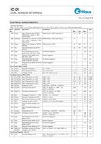
iC-DI DUAL SENSOR INTERFACE Rev C2, Page 8/15 ELECTRICAL CHARACTERISTICS Operating Conditions: VBO = 9...30 V, VBR = 9...30 V (both referenced to VN), Tj = -40...125 °C, RSET = 8.2 k ±1%, unless otherwise stated Item Symbol Parameter Conditions Unit No. Min. Typ. Max. 608 Valo() Input Threshold lo at QCFG1, QCFG2 (V() < Va()lo ) QP1, QP2 tri-state) Referenced to VCC3 (see Fig. 3) 24 29 34 % 609 Valo()hys Hysteresis lo at QCFG1, QCFG2 (V() > Valo() + Valo()hys ) QN1, QN2 active) Referenced to VCC3 (see Fig. 3) 3 7 % 610 Vpp() Open Circuit Voltage at QCFG1, QCFG2 Referenced to VCC3 42 46.5 51 %...
Open the catalog to page 8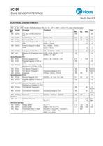
iC-DI DUAL SENSOR INTERFACE Rev C2, Page 9/15 ELECTRICAL CHARACTERISTICS Operating Conditions: VBO = 9...30 V, VBR = 9...30 V (both referenced to VN), Tj = -40...125 °C, RSET = 8.2 k ±1%, unless otherwise stated Item Symbol Parameter Conditions Unit No. Min. Typ. Max. 902 Ia(VHL) max. DC Cut-Off Current from VHL -200 mA 903 Va(VH) Cut-Off Voltage at VH Va(VH) > VHn 6.5 7.3 7.7 V 904 Va()hys Hysteresis at VH 10 25 150 mV 905 Vs(VHL) Saturation Voltage at VHL vs. VBR I(VHL) = -50mA 1.1 V I(VHL) = -150mA 3.0 V 906 Vf(VHL) Forward Voltage of Fly-Back Diode Vf() = V(GND) - V(VHL); I(VHL) = -50mA 1.5...
Open the catalog to page 9All IC-Haus catalogs and technical brochures
 Product Line Card
6 Pages
 iC-TL46 BLCC SD1C Blue LED
7 Pages
 iC212 HIGHSPEED PHOTORECEIVER
16 Pages
 Product overview
6 Pages


Archived catalogs
 iC-OV 5-Bit Optical Encoder
9 Pages
 Laser Webinar Handout
14 Pages