
Catalog excerpts
General Safety Information > o F.3.Disconnect power before servicing. 4.Release all pressure within the system beforeservicing any component.5.Drain all liquids from the system before servicingany component. Flush with water.6.Secure the outlet lines before starting the pump. Anunsecured line may whip, causing personal injury and/or property damage.7.Check hose for weak or worn condition before eachuse. Make certain that all connections are tightly secured.8.Periodically inspect the pump and the systemcomponents. Perform routine maintenance as required (See Repair Instructions).9.Use only...
Open the catalog to page 2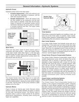
Figure 3Gerotor-TypeHydraulic Motor Closed Center Load Sensing Systems (Flow and Pressure-Compensating) Figure 1 Figure 2 Open CenterSpool Valve In Neutral Position Closed CenterSpool Valve In Neutral Position The Closed Center Flow-Compensated System is avariation of the pressure-compensated system, designed primarily for more efficient operation and the generation of less heat. It works on the principle of maintaining a constant pressure drop from the pump to the work port of the selector valve. Any variation in demand at the motor will cause a change in flow. The system senses this...
Open the catalog to page 3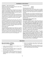
FLOAT position to allow thecentrifugal pump to come to a stop gradually. OUT )port adapter with a built-in check valveassembly will guard against reverse operation allowing you to reverse oil flow to operate other equipment. Thisadapter must not be removed. Priming the PumpThe pump must not be run dry. Standard spool valves,which are found on all tractor hydraulic systems, may cause potentially damaging high peak pressures in the hydraulic system when closed, because of abrupt shut-off of oil flow in both the supply and return lines. When shutting off the pump, move the selector to the...
Open the catalog to page 4
Adjusting Centrifugal Pump Output 1.Install a shut-off valve and pressure gauge on thedischarge line for initial setup.2.Make sure the orifice from the pressure port adapter ofthe hydraulic motor has been removed (HM2C and HM4C models only).3.Close and lock down the bypass adjusting screw in thehydraulic motor.4.Set the tractor hydraulic flow control valve for minimumhydraulic oil flow to the remote outlet (Tortoise position).5.Start the tractor and allow the hydraulic oil to circulatefor approximately 10 to 15 minutes or until adequately warmed.6.Prime the centrifugal pump with all valves...
Open the catalog to page 5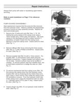
Always flush pump with water or neutralizing agent beforeservicing. Refer to parts breakdown on Page 11 for referencenumbers. PUMPHOUSING DISASSEMBLYSeal replacement requires that the pump be fully removedfrom the hydraulic motor. Observe carefully the disassembly process to ensure an easy assembly process. Replace all worn and eroded parts.1.Remove the 10 bolts and nuts (Ref. Nos. 3, 18, 19)holding the pump casing to the casing cover using a 10mm socket and a 10mm open end wrench. Tap pump casing on the discharge port with a rubber hammer, if necessary, to break it loose from the casing...
Open the catalog to page 6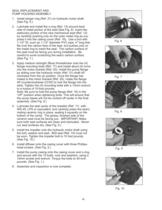
Fig. 6 Fig. 7 Fig. 8 > o clockwise from the up position. Once the flange has mated to the motor bracket (Ref. 20), rotate the flange 45 > o counterclockwise (CCW) to lock the flange into theslots. Tighten the (4) mounting bolts with a 13mm wrench to a torque of 10-foot pounds. Note: Be sure to hold the pump flange (Ref. 16) in the UPӔ position when tightening bolts. This will ensure that the pump bases will not be cocked offcenter in the final assembly. (See Fig. 8.)4.Lubricate the seal cavity of the impeller (Ref. 11) withWD-40, LPS or equivalent, and carefully press the seals mating...
Open the catalog to page 7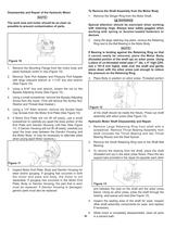
Disassembly and Repair of the Hydraulic MotorThe work area and motor should be as clean aspossible to prevent contamination of parts. To Remove the Shaft Assembly from the Motor Body 1.Remove the Slinger Ring from the Motor Shaft. Special attention should be exercised when workingwith retaining rings. Always wear safety goggles when working with spring or tension-loaded fasteners or devices. 3.Place Body in position on arbor press. Threaded portion of the shaft should be inside the fixture. Press out shaftassembly with arbor press (See Figure 12). 2.Using the large retaining ring pliers,...
Open the catalog to page 8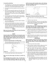
shaft and press shaft assembly down until retainingring can be installed in its groove in the bearing core of the motor body (Figure 15). Reassembly of Remaining Hydraulic Motor Parts 1.Place motor body in a vise with large end of shaft facingup.2.Install the o-ring in the body. 3.Install the Woodruff Key or Roll Pin on the shaft. Placethe Inner Gear of the gerotor onto the shaft making sure gerotor slot lines up with the key in the shaft. The Woodruff Key can slide up behind the inner gear ofthe gerotor when the gear is installed. Make sure the key is visible in the slot after the gear is...
Open the catalog to page 9
THIS WARRANTYIS EXCLUSIVE. HYPRO MAKES NO OTHER WARRANTY, EXPRESS OR IMPLIED, INCLUDING BUT NOTLIMITED TO ANYWARRANTYOF MERCHANTABILITYOR FITNESS FOR APARTICULAR PURPOSE. Hypros obligation under this warranty is, at HyproҒs option, to either repair or replace the product upon return of the entire product tothe Hypro factory in accordance with the return procedures set forth below. THIS IS THE EXCLUSIVE REMEDYFOR ANYBREACHOF WARRANTY.IN NO EVENT SHALLHYPRO BE LIABLE FOR ANYINCIDENTALOR CONSEQUENTIALDAMAGES OF ANYKIND, WHETHERFOR BREACH OF ANYWARRANTY, FOR NEGLIGENCE, ON THE BASIS OF STRICT...
Open the catalog to page 12All Hypro Pressure Cleaning catalogs and technical brochures
-
PRODUCT CATALOG
236 Pages
-
Transfer Pumps
7 Pages
-
Gear Driven
3 Pages
-
Centrifugal Pumps
41 Pages
-
9302 Series
2 Pages
Archived catalogs
-
ULD Sales Sheet
2 Pages
-
ESI Sales Sheet
2 Pages
-
TwinCap Sales Sheet
2 Pages
-
HP Stainless Steel Nozzles
2 Pages
-
UAS Ceramic Nozzles
2 Pages
-
9302 Series Sales Sheet
2 Pages
-
Hydraulic Pump Selection Guide
38 Pages
-
Foam Marker OIPM
20 Pages
-
Cleanload OIPM
12 Pages
-
Series 2100 Versa-Twin OIPM
16 Pages
-
Hydraulic Pressure Washer OIPM
20 Pages
-
PowerLine Plunger OIPM
24 Pages
-
2535S OIPM
12 Pages
-
Series 5200 Piston Pump OIPM
8 Pages
-
Series 5300 OIPM
20 Pages
-
DBS & DBA Diaphragm Pump OIPM
20 Pages


