- Catalogs
- Hypro Pressure Cleaning
- Series 9300 Hydraulic Centrifugal Operation, Installation & Parts Manual
Series 9300 Hydraulic Centrifugal Operation, Installation & Parts Manual
1 /32Pages

Series 9300 Hydraulic Centrifugal Operation, Installation & Parts Manual
1 /32Pages
Catalog excerpts

General Safety Information > o Ffor Series9300 centrifugal pumps.3.Disconnect power before servicing. 4.Release all pressure within the system beforeservicing any component.5.Drain all liquids from the system before servicingany component. Flush with water.6.Secure the outlet lines before starting the pump. Anunsecured line may whip, causing personal injury and/or property damage.7.Check hose for weak or worn condition before eachuse. Make certain that all connections are tightly secured.8.Periodically inspect the pump and the systemcomponents. Perform routine maintenance as required (See Repair...
Open the catalog to page 2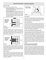
Figure 3Gerotor-TypeHydraulic Motor Closed Center Load Sensing Systems (Flow and Pressure-Compensating) Figure 1Open CenterSpool Valve InNeutral Position The Closed Center Flow-Compensated System is avariation of the pressure-compensated system, designed primarily for more efficient operation and the generation of less heat. It works on the principle of maintaining a constant pressure drop from the pump to the work port of the selector valve. Any variation in demand at the motor will cause a change in flow. The system senses this change in flow due to the change in pressure drop across the valve...
Open the catalog to page 3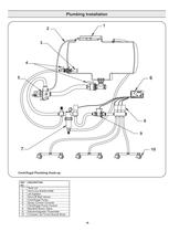
REF.DESCRIPTION NO. 1Tank Lid 2Vent Line #3430-0456 3Jet Agitator 4Shut-offBall Valves 5Centrifugal Pump 6Spray Control Console 7Centrifugal Pump Control 8Manifold Boom Valve 9Electromagnetic Flowmeter10Compact Jet Turret Nozzle Body >
Open the catalog to page 4
Controlling the Pump Flow Centrifugal Pump Control The best way to control the flow is by incorporating twocontrol valves in a pipe tee immediately after the strainer in the discharge line. This permits controlling agitation flow independently of nozzle flow.In any centrifugal pump, it is the large volume of liquid whichputs load on the drive. Use only the flow needed to develop the pressure required at the boom and to maintain adequate agitation. Hydraulic motor-driven centrifugal pumps are easily adjusted to the exact flow required, as explained in the Operating Instructions of this manual....
Open the catalog to page 5
OUT )port adapter with a built-in check valveassembly will guard against reverse operation allowing you to reverse oil flow to operate other equipment. Thisadapter must not be removed. On HM2C and HM4Cmodel pumps, the pressure ( IN )port adapter is a two-pieceassembly consisting of an open (unrestricted) adapter with three orifices packed loose with the pump. (See the Operations Section.) Agitation Nozzle Bodies > The centrifugal pump control contains a manual agitationcontrol valve that can be adjusted to provide the right amount of flow to the jet agitators in the tank to ensure proper mixing...
Open the catalog to page 6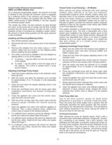
Adjusting Centrifugal Pump Output 1.Make sure the orifice from the pressure port adapter ofthe hydraulic motor has been removed (HM2C and HM4C models only).2.Close and lock down the bypass adjusting screw in thehydraulic motor.3.Set the tractor hydraulic flow control valve for minimumhydraulic oil flow to the remote outlet (Tortoise position).4.Start the tractor and allow the hydraulic oil to circulatefor approximately 10 to 15 minutes or until adequately warmed.5.Prime the centrifugal pump with all valves open (Seethe Installation Instructions and System Configuration Diagram).6.Close the agitation...
Open the catalog to page 7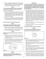
]7.Install the o-ring on the mounting flange. Replace theo-ring if worn or damaged.8.Place the pump casing on the mounting flange, insertand tighten the bolts. 3.Using a screwdriver and hammer, tap out the stationaryportion of the Mechanical Seal from the motor side of the Mounting Flange. (If the motor is not removed, the seal can be pried out with a small screwdriver.) Onpolypropylene models, insert the Woodruff Key into the Shaft key slot. Place the Impeller on the Shaft and align it with the Key; then press against the Mechanical Seal Assembly. Place the Metal Seal Washer on the Shaft. Apply...
Open the catalog to page 9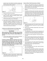
apart the boss area between the Gerotor Housing andthe Motor Body. (It may be necessary to alternate sides when prying apart Motor sections.) Hydraulic Motor Shaft Disassembly and Repair 1.Remove Large Retaining Ring from Shaft with ascrewdriver. Remove Thrust Bearing Assembly from Shaft (includes the Thrust Bearing and two Thrust Bearing Races) and the Seal Spacer.2.Remove the Small Retaining Ring next to the Shaft BallBearing. Figure 11 3.To remove the Bearing from the shaft, place the shaft(threaded end up) in the arbor press fixture. Place the two support bars provided in the repair kit opposite...
Open the catalog to page 10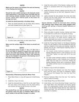
4.Install the outer portion of the Gerotor, making sure theGerotor is centered within the o-ring groove on the body.5.Install the Gerotor Housing, making sure the pins in theGerotor Housing line up with their respective holes in the body.6.Lightly lubricate the area between the Inner and OuterGerotor and the Outer Gerotor and Gerotor Housing with hydraulic oil or mineral oil. Special attention should be exercised when workingwith retaining rings. Always wear safety goggles when working with spring or tension-loaded fasteners or devices. 7.Install o-ring on the motor end plate. 8.Place end plate...
Open the catalog to page 11
SymptomProbable Cause(s)Corrective Action(s) Low dischargePump not primed.Remove topmost vent plug from face of pump and run pump to expel trapped air (See Installation Instructions).Air leaks in inlet line.חCheck and reseal inlet fittings. Blocked or clogged line strainer.Inspect strainer and clear any debris from screen. Impeller plugged.חInspect and clear obstruction. Undersize inlet line orSuction line should be the same diameter as inlet port of pump or larger. collapsed hose. Improperly sized hydraulic motor.חRefer to Pump Selection Guide to determine proper size hydraulic motor for your...
Open the catalog to page 12
050100150200250300350400450 1009080706050403020100020406080100120 02134561-1/2˝ Inlet Hose Feet of lift = 151050 >
Open the catalog to page 13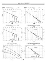
203040 10001050607080304020 Feet of Lift = 151050 1-1/2˝ Inlet Hose >
Open the catalog to page 14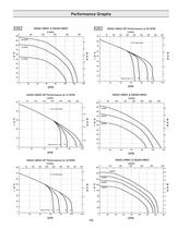
050100150200250300350450450 405060708090 2030100020801001206040 Feet of Lift = 151050 1-1/2˝ Inlet Hose 0123456 050100150200250300350 304050 20100020801006040 Feet of Lift = 151050 1-1/2˝ Inlet Hose 010.51.522.53 > 050100150200250300350450450 304050607080 20100020801001206040 Feet of Lift = 151050 1-1/2˝ Inlet Hose 01234 5 >
Open the catalog to page 15All Hypro Pressure Cleaning catalogs and technical brochures
 PRODUCT CATALOG
236 Pages
 Transfer Pumps
7 Pages
 Gear Driven
3 Pages
 Centrifugal Pumps
41 Pages
 9302 Series
2 Pages

Archived catalogs
 DBS & DBA Diaphragm Pump OIPM
20 Pages
 Series 2100 Versa-Twin OIPM
16 Pages
 Hydraulic Pressure Washer OIPM
20 Pages
 Hydraulic Pump Selection Guide
38 Pages
 9302 Series Sales Sheet
2 Pages
 UAS Ceramic Nozzles
2 Pages
 HP Stainless Steel Nozzles
2 Pages
 TwinCap Sales Sheet
2 Pages
 ULD Sales Sheet
2 Pages
 ESI Sales Sheet
2 Pages
 Series 5300 OIPM
20 Pages
 2535S OIPM
12 Pages
 PowerLine Plunger OIPM
24 Pages
 Cleanload OIPM
12 Pages
 Foam Marker OIPM
20 Pages
 Series 5200 Piston Pump OIPM
8 Pages


