- Catalogs
- Hypro Pressure Cleaning
- Gear & Belt Drive Centrifugal Operation, Installation & Parts Manual
Gear & Belt Drive Centrifugal Operation, Installation & Parts Manual
1 /24Pages

Gear & Belt Drive Centrifugal Operation, Installation & Parts Manual
1 /24Pages
Catalog excerpts
Notes are used to notify of installation, operation, ormaintenance information that is important but not safety related.Caution is used to indicate the presence of a hazard,which will or may cause minor injury or property damage if the notice is ignored.Warning denotes that a potential hazard exists andindicates procedures that must be followed exactly to either eliminate or reduce the hazard, and to avoid serious personal injury, or prevent future safety problems with the product.Danger is used to indicate the presence of a hazardthat will result in severe personal injury, death, or property...
Open the catalog to page 2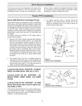
This manual will cover the installation of the basic driveconfigurations available for belt and gear-drive Hypro Centrifugal Pumps. Consult the manufacturer of yourtractor, motor or engine for additional information. Read all instructions and general safety information before attempting to install or operate the pump. > 3. To prevent start-up shock, a Spring should beattached to the Torque Chain. Secure end of the Spring to something solid in the same manner as using a Torque Chain alone. Series 9400 Pumps are designed for ease of installation and removal with tractor-mounted sprayers. Hollow...
Open the catalog to page 3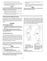
1.Slide Locking Collar onto Pump Driver Shaft.2.Thread the longer Set Screw " 5.Tighten Set Screw " A "very securely with a 3/16"allen wrench.6.Tighten Set Screw " A "through theLocking Collar and partially through the threaded hole in the Pump Driver Shaft. B "very securely with the samewrench. This binds Set Screw " A "which prevents itfrom coming loose. It is necessary to allow a minimum of 1/8" clearancebetween the Locking Collar and the Pump Driver Shaft at Set Screw "A" (See Figure 2). 3.Thread the shorter set screw " B "into the otherthreaded hole in the Locking Collar.4.Slide Pump Driver...
Open the catalog to page 4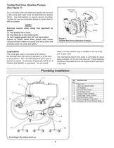
ChainTorque Arm Pump GearCase Spring o REF.DESCRIPTION NO. 1Tank Lid 2Vent Line #3430-0456 3Jet Agitator 4Shut-off Ball Valves 5Centrifugal Pump 6Spray Control Console 7Centrifugal Pump Control 8Manifold Boom Valve 9Electromagnetic Flowmeter10Compact Jet Turret Nozzle Body >
Open the catalog to page 6
Nozzle Bodies Nozzle bodies with shut-off check valves are recom- mended to eliminate dripping from the spray tips when the boom valves are shut down. Boom Section Valves For rapid response and reliability,we recommend elec- tric plunger valves be used for boom control. The valves should be sized accordingly to minimize the pressure drop and maximize the flow rate. The boom tubing or hose should be sized accordingly to ensure that a pres- sure drop in the lines does not occur,causing inconsis- tent pressures at the nozzles. Agitation Flowmeter The centrifugal pump control contains a manual agitation...
Open the catalog to page 7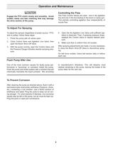
Engage the PTO clutch slowly and smoothly. Avoidsudden starts and fast clutching that may damage the drive section of the pump. Two Flow Control Valves are used - one in the agitation line and one in the line leading to the boom or spray gun. This permits controlling agitation flow independently of nozzle flow. > To adjust the sprayer (regardless of power source - PTO, belt or pulley), follow these steps:1. Prime the pump with all valves open. 2.Close Control Valve and Agitation Line Valve; thenopen the Boom ShutOff Valve.3. With the pump running, open the Control Valve untilthe Pressure Gauge...
Open the catalog to page 8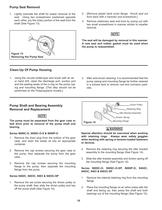
Remove plastic back cover flange. Knock seal outfrom back with a hammer and screwdriver.] > 3. Remove stationary seat and boot by prying out withtwo small screwdrivers in manner similar to impeller removal. 1.Lightly lubricate the shaft for easier removal of theseal. Using two screwdrivers positioned opposite each other, pry the rotary portion of the seal from the shaft (See Figure 13).2.[ The seal will be damaged by removal in this manner.Anew seal and rubber gasket must be used when the pump is reassembled. Figure 13 Removing the Pump Seal > This step should not beperformed on the Polypropylene...
Open the catalog to page 10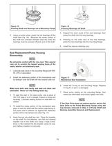
Figure 15 Figure 16 Pressing Bearings off Shaft Pressing Shaft and Bearings out of Mounting Flange 3.Using an arbor press, press the old bearings off theshaft (See Fig. 16). Because the center portion of the shaft has a thicker diameter than the ends, the bearings must be pressed off each end of the shaft.4.Support the inner races of the new bearings; thenpress the shaft into the new bearings.5.Pressing on the outer race of the new bearings,press the new bearings into the mounting flange.6.Install the internal retaining ring. > Be extremely careful with the new seal. Take special care not to...
Open the catalog to page 11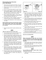
Gear Drive Unit ReassemblyBefore reassembling the gear drive unit, all partsshould be examined, and parts being reused should be clean and free of old oil. DO NOT WASH MAIN BEARING. 1.Place the gear case in the press, face up. Press themain bearing in (See Figure 22). Insert a large retain- er ring into the gear case.2.Place the gear case in the press, face up. Positionthe driver hub in the main bearing and press in, bot- toming on the main bearing. > On the 1000 rpm models, perform Step 5 beforeinstalling the driver hub. 1.Remove the drain plug from the bottom of the gearcase and drain the waste...
Open the catalog to page 12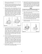
The weep holes in the mounting flange adapter must face down - towards feet. Do not force together. 12.Align holes and secure with gear case capscrews,using a 9/16" socket wrench.13.Replace the bottom drain plug in the gear case andremove the top fill plug. Fill the gear case with approximately 6oz. of Phillube SAE 80W90 GearOil. DO NOTOVERFILL. Replace the breather plug. DO NOTuse the side plugs on the gear case for a fill level indicator because doing so will cause you to overfill and damage the gear case.14.Install the pump seal, impeller and pump casing asdescribed elsewhere. 4.Slide a new...
Open the catalog to page 13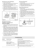
Idler Bearing Replacement 1.Remove the belt.2.Remove the idler bolt with a 15/16" impact socket. 3.Remove the idler pulley snap ring. 4.Press out the bearing using an arbor press. 5.To reassemble, reverse the procedure. Pedestal Bearing Replacement 1.Remove the belt.2.Remove the large pulley retainer ring and pulley.(For quick coupled models, remove the outer keeper ring and keeper balls.)3.Remove the bearing retainer ring and dust cover. 4.Using an arbor press, press out the driver hub andbearing assembly from the pedestal bearing bore.5.Remove the bearing snap ring from the shaft. 6.Using the...
Open the catalog to page 14All Hypro Pressure Cleaning catalogs and technical brochures
 PRODUCT CATALOG
236 Pages
 Transfer Pumps
7 Pages
 Gear Driven
3 Pages
 Centrifugal Pumps
41 Pages
 9302 Series
2 Pages

Archived catalogs
 DBS & DBA Diaphragm Pump OIPM
20 Pages
 Series 2100 Versa-Twin OIPM
16 Pages
 Hydraulic Pressure Washer OIPM
20 Pages
 Hydraulic Pump Selection Guide
38 Pages
 9302 Series Sales Sheet
2 Pages
 UAS Ceramic Nozzles
2 Pages
 HP Stainless Steel Nozzles
2 Pages
 TwinCap Sales Sheet
2 Pages
 ULD Sales Sheet
2 Pages
 ESI Sales Sheet
2 Pages
 Series 5300 OIPM
20 Pages
 2535S OIPM
12 Pages
 PowerLine Plunger OIPM
24 Pages
 Cleanload OIPM
12 Pages
 Foam Marker OIPM
20 Pages
 Series 5200 Piston Pump OIPM
8 Pages


