
- Catalogs
- Hypro Pressure Cleaning
- DBS & DBA Diaphragm Pump OIPM

DBS & DBA Diaphragm Pump OIPM

DBS & DBA Diaphragm Pump OIPM
This document provides comprehensive details on specifications, installation, operation, and maintenance for high-pressure diaphragm pumps, specifically models 9910-DBS200, 9910-DBA200, 9910-DBS160, 9910-DBA160, 9910-DBS140, 9910-DBA140, 9910-DBS110, and 9910-DBA110, designed for high-pressure applications like chemical spraying and cleaning.
- Models 9910-DBS200 and 9910-DBA200: Max flow 49.8 gpm, Max pressure 725 psi, Max speed 550 rpm, 4 diaphragms.
- Models 9910-DBS160 and 9910-DBA160: Max flow 39.7 gpm, Max pressure 725 psi, Max speed 550 rpm, 4 diaphragms.
- Models 9910-DBS140 and 9910-DBA140: Max flow 37.6 gpm, Max pressure 725 psi, Max speed 550 rpm, 3 diaphragms.
- Models 9910-DBS110 and 9910-DBA110: Max flow 28.5 gpm, Max pressure 725 psi, Max speed 550 rpm, 3 diaphragms.
- 9910-GH50: Controls pressure up to 725 psi and flow up to 51 gpm, suitable for all models.
- 9910-BMH50: Controls pressure up to 725 psi and flow up to 41 gpm, suitable for 110, 140, and 160 series.
- Do not pump flammable or explosive fluids.
- Avoid using hands to check hydraulic lines; use cardboard instead.
- Wear hearing protection if sound levels exceed 80dBA.
- Operate within a temperature range of 45˚ to 140˚ F.
- Ensure all connections are tight and secure.
- Mount the pump with the oil sight tube upright.
- Use high-quality hoses compatible with the fluids being pumped.
- Secure all connections with good quality hose clamps.
- Ensure oil is at the correct level in the sight tube.
- Check charge pressure on the pulsation dampener.
- Start the pump under low pressure and adjust to desired pressure.
- Flush the pump with clean water after use.
- Change oil every 500 hours or three months, using Hypro Oil.
- For winter storage, flush with a water and antifreeze mixture.
- Irregular flow or noise may indicate valve issues or incorrect pulsation damper charge.
- Milky oil or oil discharge may indicate diaphragm issues.
- Replace diaphragms every 500 hours or three months.
- Check and replace valves and o-rings as needed.
- Direct and remote mounting instructions provided for control units 9910-GH50 and 9910-BMH50.
- Ensure all connections use hoses rated for maximum pressure.
1. Remove the outlet elbow from the control unit, retaining the bolts and ensuring the o-ring is not misplaced.
2. Attach the adapter elbow flange to the port using thread sealant and tighten to the desired orientation.
3. Ensure the o-ring is in place on the flange, then attach the control unit and secure with bolts.
4. Connect the bypass hose to the bypass port fitting and run it back to the tank.
5. Connect lines to the outlet port hose barbs, shutting off unused ports with a ball valve or plugging them.
1. Use Kit No. 9910-KIT999 to attach the remote mounting bracket to the control unit.
2. Connect the hose barb fitting to the bypass outlet, ensuring the o-ring is in place.
3. Connect the adapter elbow flange to the NPT elbow at the pump's discharge manifold.
4. Connect the bypass hose to the bypass port hose barb and run it back to the tank.
5. Connect lines to the outlet port hose barbs, shutting off unused ports with a ball valve or plugging them.
1. Refer to pump operation instructions for proper use.
2. To enter full bypass mode, rotate the control lever to the 10:30 position.
3. To control the right outlet port, rotate the lever to the 4:30 position.
4. To control the left outlet port, rotate the lever to the 7:30 position.
5. To control both booms, rotate the lever to the 6:00 position.
6. To maintain pressure without flow, rotate the lever to the 2:30 position.
7. Adjust pressure using the knob at the relief valve; clockwise increases pressure, counterclockwise decreases it.
The document includes detailed parts lists for various models and kits, such as the 9910-BMH50 control unit and remote mounting kits. It specifies part numbers, descriptions, and quantities required for assembly and maintenance.
The document provides torque specifications for various components and performance data for different RPMs and pressures, both in English and Metric units.
The document provides detailed performance charts for various series of pumps (200, 110, and 140 Series) in both English and Metric standards. The charts list performance metrics such as PSI, GPM (gallons per minute), HP (horsepower), and L/M (liters per minute) at different RPMs (350, 450, 500, 550). These metrics are crucial for understanding the efficiency and capacity of the pumps under different operational conditions.
Hypro offers a warranty to the original purchaser, covering defects in material and workmanship under normal use for one year for most products, five years for oil crankcase plunger pumps, and ninety days for accessories. The warranty excludes damages from excessive use, incompatible fluids, freight damage, freezing, normal wear and tear, and misapplication. The warranty is exclusive, with no implied warranties of merchantability or fitness for a particular purpose.
Products must be flushed of chemicals and labeled before being returned for service or warranty consideration. Hypro may request a Material Safety Data sheet and reserves the right to dispose of products containing unknown substances. For service or warranty assistance, contact Hypro with detailed information about the product and issue, including model number, purchase details, and specifics about the problem.
For technical assistance, call Hypro Technical/Application at 1-800-445-8360. For service or warranty assistance, call 1-800-468-3428 or fax (651) 766-6618. Products returned for warranty work should be sent prepaid to Hypro's Service Department in New Brighton, Minnesota.
Catalog excerpts
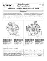
Heavy-duty, high pressure diaphragm pumps. These industrial-built pumps are designed to handle all of your high pressure and volume diaphragm pump needs with minimal maintenance required. Their innovative, external manifold design allows for normal servicing to be done from one side of the pump, thereby eliminating the needfor dismounting. These pumps are excellent for chemicalspraying where higher pressures are desired, such as insecticide spraying, air blast and tall tree sprayers. They also work great for high pressure cleaning and dis- infecting applications, such as poultry house cleaners. Control Units 9910-GH50 & 9910-BMH50 > Control units are available for easy flow and pressurecontrol of your sprayer system. These units include a pressure relief valve to control pressure, an oil-filled pres- sure gauge to monitor pressure, and an outlet valve to control flow. Control unit 9910-BMH50 can be remote mounted with Kit No. 9910-KIT999. Refer to the adjoining chart to select the proper control unit for your pump. > Max flow: 28.5 gpm Max flow: 37.6 gpm Max flow: 39.7 gpm Max flow: 49.8 gpm Max pressure: 725 psi Max pressure: 725 psi Max pressure: 725 psi Max pressure: 725 psi Max speed: 550 rpm Max speed: 550 rpm Max speed: 550 rpm Max speed: 550 rpm 3Diaphragms 3Diaphragms 4Diaphragms 4Diaphragms ControlMax.Max.PumpUnit ModelGPMPSIModel 9910-GH5051725All models9910-BMH5041725All 110,140 and 160 Series >
Open the catalog to page 1
Notes are used to notify of installation, operation, or maintenance information that is important but not safety related.Caution is used to indicate the presence of a hazard,which will or can cause minor injury or property damage if the notice is ignored. Warning denotes that a potential hazard exists andindicates procedures that must be followed exactly to either eliminate or reduce the hazard, and to avoid serious personal injury, or prevent future safe- ty problems with the product. Danger is used to indicate the presence of a hazard thatwillresult in severe personal injury, death, or property...
Open the catalog to page 2
The pump does not draw water.The liquid flow is irregular.Output drops and the pump is noisy.Oil comes out of the discharge portor oil is a milky color. One or more valves are seating improperly.Suction line is plugged or col-lapsed. Clogged strainer.The charge in the pulsationdamper is incorrect.One or more valves are seatingimproperly.Oil level is too low. One or more diaphragms split. Remove valve and check for debris.Examine suction line. Clean strainer.Check pressure in pulsation damper(approximately 20% of your operat- ing spray pressure).Remove valve and check for debris.Examine the valve...
Open the catalog to page 4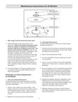
II.Diaphragm Replacement Change diaphragms every 500 hours or three months, whichever comes first.1.Drain the oil from the pump by removing the cap fromoil sight tube and removing the oil drain plug. Rotate the shaft to remove excess oil. 2.Remove the head bolts and heads. 3.Turn the crankshaft to bring the retaining bolt as farout as possible.4.Use a 13 mm box wrench to remove the diaphragmretaining nut. Remove the nut, retaining washer and diaphragm. 5. When reinstalling, turn the crankshaft to bring the pis-ton to its downstroke and seat the new diaphragm into the sleeve groove. Install the...
Open the catalog to page 5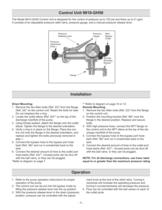
The Model 9910-GH50 Control Unit is designed for the control of pressure up to 725 psi and flows up to 51 gpm. It consists of an adjustable pressure relief valve, pressure gauge, and a manual pressure release lever. > Pressure Release LeverPressure GaugeMainBypass OutletRemote Mounting BracketFlange Pressure Adjustment Knob 1.Remove the two Allen bolts (Ref. 23)* from the flangeon the control unit.2.Position the mounting bracket (Ref. 66)* over theflange in the desired position. Replace and secure bolts.3.With high pressure hose, connect the NPTflange onthe control unit to the NPTelbow at the...
Open the catalog to page 6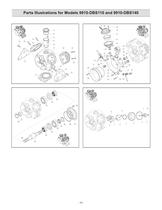
Parts Illustrations for Models 9910-DBS110 and 9910-DBS140 Model 9910-DBS-110, 9910-DBS-140 > -10- size="-1">
Open the catalog to page 10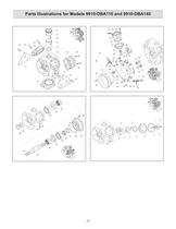
Parts Illustrations for Models 9910-DBA110 and 9910-DBA140 Model 9910-DBS-110, 9910-DBS-140 > -14- size="-1">
Open the catalog to page 14
Hypro warrants to the original purchaser of its products (the PurchaserӔ) that such products will be free from defects in materialand workmanship under normal use for the period of one (1) year for all products except: oil crankcase plunger pumps will be freefrom defects in material and workmanship under normal use for the period of five (5) years, and accessories will be free from defects in material and workmanship under normal use for the period of ninety (90) days. In addition, Hypro warrants to the pur-chaser all forged brass pump manifolds will be free from defects in material and workmanship...
Open the catalog to page 20All Hypro Pressure Cleaning catalogs and technical brochures
 PRODUCT CATALOG
236 Pages
 Transfer Pumps
7 Pages
 Gear Driven
3 Pages
 Centrifugal Pumps
41 Pages
 9302 Series
2 Pages

Archived catalogs
 Series 2100 Versa-Twin OIPM
16 Pages
 Hydraulic Pressure Washer OIPM
20 Pages
 Hydraulic Pump Selection Guide
38 Pages
 9302 Series Sales Sheet
2 Pages
 UAS Ceramic Nozzles
2 Pages
 HP Stainless Steel Nozzles
2 Pages
 TwinCap Sales Sheet
2 Pages
 ULD Sales Sheet
2 Pages
 ESI Sales Sheet
2 Pages
 Series 5300 OIPM
20 Pages
 2535S OIPM
12 Pages
 PowerLine Plunger OIPM
24 Pages
 Cleanload OIPM
12 Pages
 Foam Marker OIPM
20 Pages
 Series 5200 Piston Pump OIPM
8 Pages


