- Catalogs
- Hypro Pressure Cleaning
- Cast Iron Transfer Pump Operation, Installation & Parts Manual
Cast Iron Transfer Pump Operation, Installation & Parts Manual
1 /16Pages

Cast Iron Transfer Pump Operation, Installation & Parts Manual
1 /16Pages
Catalog excerpts
WARNING: Gasoline is a highly combustible fuel. Theimproper use, handling, or storage of Gasoline can be dangerous. Never touch or fill a hot engine. 8.Use only pipe, hose and fittings rated for the maximumpsi rating of the pump.9.Do not use these pumps for pumping water or otherliquids for human or animal consumption. > WARNING: Do not pump flammable or explosive fluids such as Gasoline, Fuel Oil, Kerosene, etc. Do not use inexplosive atmospheres. The pump should be used only with liquids that are compatible with the pump component materials. Failure to follow this Warning can result in Personal...
Open the catalog to page 2
Please Note: It is illegal to ship or transport any hazardous chemicals without United States Environmental Protection Agency Licensing. 1.Always drain and flush pumps before servicing ordisassembling for any reason.2.Before returning unit for repair, drain out all liquids andflush unit with neutralizing liquid. Then, drain the pump. Attach a tag or include a written notice certifying that this has been done. 3.Never store pumps containing hazardous chemicals. When engine is cold: In cold weather, start engine with choke in fully closed position.In warm weather, start engine with choke in half-closed...
Open the catalog to page 3
Note: When removing adapter, be careful not to damage paper gasket betweenadapter and pump.Note: Mechanical seal will be exposed after adapter is removed. Be careful notto damage seal faces. > (Figure 1)1.Remove two-bolt clamp from pump shaft. (Figure 2) 2.Remove (6) nuts and lock washers holding adapter to pump. (Figure 3) Note: Prior to assembly, visually inspect pump outlet for impeller spacer.Pumps are supplied with a strip of plastic banding inserted into the pump outlet and across the impeller face to ensure proper impeller spacing. If the banding is in place, proceed to step 10. If banding...
Open the catalog to page 4
1.Remove two-bolt clamp and bolts. (Figure 9)2.Remove (4) mounting bolts between pump adapter and engine, motor, orpedestal. (Figure 10)3.Remove engine, motor, or pedestal. Drive source may need to be pried off. Usecaution not to damage drive source or pump.4.Remove (6) nuts and lock washers holding adapter to pump. (Figure 11) Note: Mechanical seal will be exposed after adapter is removed. Be carefulnot to damage seal faces. 5.Gently pry the adapter flange off using a pry bar against tabs on the adapter.(Figure 12)6.Remove impeller, drive sleeve, mechanical seal assembly. 7.Remove paper gasket...
Open the catalog to page 6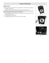
Inspect wear plate for excessive wear, surface grooves or impeller contact. Replaceifneeded. (Figure 13)1.Remove two 3/8 stainless steel screws from wear ring. (Figure 14) Note: Older models have acorn nuts and plastic washers on the front of thepump. If equipped, remove these first. (Figure 15) 2.Install new wear ring, making sure pump surface and ring are clean and the ringsits flat against the pump.3.Reinstall stainless steel screws. 4.Reinstall plastic washers, and acorn nuts on older models. >
Open the catalog to page 7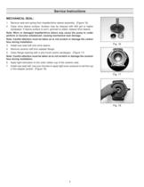
1.Remove seal and spring from impeller/drive sleeve assembly. (Figure 16)2.Clean drive sleeve surface. Surface may be cleaned with 400 grit or highersandpaper. If sleeve surface is worn, grooved or pitted, replace drive sleeve. Note: Worn or damaged impeller/drive sleeve may cause the pump to underperform or become unbalanced, causing mechanical seal damage.Note: Careful attention must be taken as to not scratch or damage the carbonface during installation. Note: Careful attention must be taken as to not scratch or damage the ceramicface during installation. 6.Apply light lubrication to the outer...
Open the catalog to page 8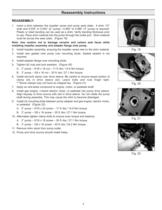
Note: Use caution not to damage ceramic and carbon seal faces whileinstalling impeller assembly and adapter flange onto pump. 1.Insert a shim between the impeller vanes and pump wear plate. Ashim 1/2wide and 0.035Ԕ to 0.040 (2Ԕ pump) / 0.060 to 0.066Ԕ (3 pump) is required. Plastic or steel banding can be used as a shim. Verify banding thickness prior touse. Place shim material into the pump through the outlet port. Shim material must lie across the wear plate. (Figure 19) 2.Install impeller assembly, ensuring the impeller vanes rest on the shim material.3.Install new gasket onto pump over mounting...
Open the catalog to page 9
PROBABLE CAUSE SYMPTOMENGINEPUMPSYSTEM ABCDEFGHIJKLMNOP XXXXXXX Pump works for a while, then stops XXXXXX CAUSECORRECTIVE ACTION 1. ENGINE A.Speed too low.Refer to engine section. B.Rotating and/or reciprocating parts drag.Refer to engine section. C.Speed too high.Maximum engine speed not to exceed engine manufacturers recommendation. D.Loose or broken parts.Refer to engine section. 2. PUMP E.Not primed.Reprime, inspect suction system for air leaks, and/or check assembly. F.Pump takes too long to prime.Check for air leaks or defective check valve.G.Flow through pump completely Locate and remove...
Open the catalog to page 10
Add Gasoline Fill gas tank with clean, fresh gasoline. This should beunleaded fuel that has an octane rating of 86 or higher. Do not fill the tank to overflowing. Clean up any spilledgasoline before starting the engine. > Engine Safety Precautions:Fire and explosion hazard. Gasoline canexplode. Store gasoline away from the engine. Add gaso- line to the engine only when the engine is off. Burn hazard. Hot surface. The engine getsvery hot during operation. Do not touch the engine sur- faces. Keep children away. Allow the engine to cool before moving it indoors. Deadly fumes. Carbon monoxide. Never...
Open the catalog to page 11
Air Filter The oil level should be checked before each use. If the engine wont start:ҕCheck that there is gas in the tank. Make sure the fuel valve is ՓON and that the engineswitch is ԓON.ԕMake sure there is enough oil in the engine to reset thelow-oil sensor.Check that fuel is getting to the carburetor.* ՕCheck for spark at the spark plug.** The air filter should be checked every month for dust anddirtaccumulation. Every 6 months, the filter element should be removed and cleaned. Clean the foam element with detergent and warm water. Squeeze out excess water and let it dry. Before reinstalling...
Open the catalog to page 12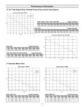
GPM atGPM atGPM atGPM atGPM atGPM atGPM atGPM atGPM atGPM atGPM atGPM atGPM at 0PSI5 PSI10 PSI15 PSI20 PSI25 PSI30 PSI35 PSI40 PSI45 PSI50 PSI60 PSI66 PSI > GPM atGPM atGPM atGPM atGPM atGPM atGPM atGPM atGPM atGPM atGPM atGPM atGPM atGPM at 0PSI5 PSI10 PSI15 PSI20 PSI25 PSI30 PSI35 PSI40 PSI45 PSI50 PSI55 PSI60 PSI61 PSI > GPM atGPM atGPM atGPM atGPM atGPM atGPM atGPM atGPM at 0PSI5 PSI10 PSI15 PSI20 PSI25 PSI30 PSI35 PSI40 PSI > GPM atGPM atGPM atGPM atGPM atGPM atGPM atGPM atGPM atGPM at 0PSI5 PSI10 PSI15 PSI20 PSI25 PSI30 PSI35 PSI40 PSI42 PSI > Hyd.FlowGPM atGPM atGPM atGPM atGPM atGPM atGPM...
Open the catalog to page 13All Hypro Pressure Cleaning catalogs and technical brochures
 PRODUCT CATALOG
236 Pages
 Transfer Pumps
7 Pages
 Gear Driven
3 Pages
 Centrifugal Pumps
41 Pages
 9302 Series
2 Pages

Archived catalogs
 DBS & DBA Diaphragm Pump OIPM
20 Pages
 Series 2100 Versa-Twin OIPM
16 Pages
 Hydraulic Pressure Washer OIPM
20 Pages
 Hydraulic Pump Selection Guide
38 Pages
 9302 Series Sales Sheet
2 Pages
 UAS Ceramic Nozzles
2 Pages
 HP Stainless Steel Nozzles
2 Pages
 TwinCap Sales Sheet
2 Pages
 ULD Sales Sheet
2 Pages
 ESI Sales Sheet
2 Pages
 Series 5300 OIPM
20 Pages
 2535S OIPM
12 Pages
 PowerLine Plunger OIPM
24 Pages
 Cleanload OIPM
12 Pages
 Foam Marker OIPM
20 Pages
 Series 5200 Piston Pump OIPM
8 Pages


- Industrial pump
- Pump with electric motor
- Centrifugal pump
- Self-priming pump
- Chemical pump
- Control valve
- Water valve
- Stainless steel pump
- Transfer pump
- Diaphragm pump
- Pressure gauge
- Piston pump
- Pressure limiter
- Hydraulic pump
- Single-stage pressure regulator
- Materials handling pump
- Cast iron pump
- Industrial pressure limiter