
Catalog excerpts
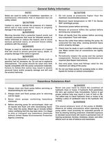
1.Do not pump at pressures higher than themaximum recommended pressure.2.Maximum liquid temperature is 140 > o Ffor Series9307 centrifugal pumps.3.Disconnect power before servicing. 4.Release all pressure within the system beforeservicing any component.5.Drain all liquids from the system before servicingany component. Flush with water.6.Secure the outlet lines before starting the pump. Anunsecured line may whip, causing personal injury and/or property damage.7.Check hose for weak or worn condition before eachuse. Make certain that all connections are tightly secured.8.Periodically inspect...
Open the catalog to page 2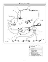
REF.DESCRIPTION NO. 1Tank Lid 2Vent Line #3430-0456 3Jet Agitator 4Shut-offBall Valves 5Centrifugal Pump 6Spray Control Console 7Centrifugal Pump Control 8Manifold Boom Valve 9Electromagnetic Flowmeter10Compact Jet Turret Nozzle Body >
Open the catalog to page 3
Agitation Controlling the Pump Flow Centrifugal Pump Control The centrifugal pump control contains a manual agitationcontrol valve that can be adjusted to provide the right amount of flow to the jet agitators in the tank to ensure proper mixing within the tank. Flowmeter Boom Section Valves The best way to control the flow is by incorporating twocontrol valves in a pipe tee immediately after the strainer in the discharge line. This permits controlling agitation flow independently of nozzle flow.In any centrifugal pump, it is the large volume of liquid whichputs load on the drive. Use only...
Open the catalog to page 4
Adjusting Centrifugal Pump Output 1.Set the tractor hydraulic flow control valve for minimumhydraulic oil flow to the remote outlet (Tortoise position).2.Start the tractor and allow the hydraulic oil to circulatefor approximately 10 to 15 minutes or until adequately warmed.3.Prime the centrifugal pump with all valves open (Seethe Installation Instructions and System Configuration Diagram).4.Close the agitation line valve and open the control valveand the boom shut-off valve.5.Slowly adjust the tractor hydraulic flow control valve untilthe desired boom pressure is attained.6.Open the...
Open the catalog to page 5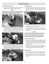
Pump Seal Removal 1.Using a 3/4" wrench, remove the eight Hex Head Boltsholding the Pump Casing to the Mounting Flange. 1.Lightly lubricate the shaft for easier removal of the seal.Using two screwdrivers positioned opposite each other, pry the rotary portion of the seal from the shaft (See Figure 5). Once removed, turn the cover until mounting holes areexposed. Place a screwdriver on each side of the cover and pry away the mounting flange (See Figure 2). The seal will be damaged by removal in this manner. Anew seal must be used when pump is reassembled.In the case of a severe pump seal...
Open the catalog to page 6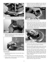
4.Spread the snap ring by grabbing the open ends andpulling them apart, like extending a spring. Guide the retaining ring into the mounting flange using a screwdriver for assistance (See Figure 9). 5.Install the slinger onto the pump shaft.6.Using soap and water as a lubricant, install thestationary half of the mechanical seal into the seal flange. Press it into place using a rag over the seal face and a 1-3/8 plastic guide (See Figure 10). Assemble the seal flange and mechanical seal. Assemble onto the mounting flange, taking care to avoid hitting the mechanical seal on the pump shaft....
Open the catalog to page 7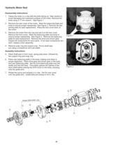
Disassembly Instructions 1. Clamp the motor in a vise with the bolts facing up. Take caution toavoid damaging the machined surfaces of the motor. Remove the bolts using a 17 mm wrench. See Figure 1.2. Remove the rear cover of the motor. Mark the balancing plate andbody to ensure proper reassembly. See Figure 2. Remove the bal- ancing plate for seal replacement. Place the rear cover back on the motor.3.Remove the motor from the vise and set it on the rear cover.Remove the front cover. Mark the balancing plate and body to ensure proper reassembly. See Figure 2. Remove the balancing plate for...
Open the catalog to page 8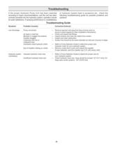
SymptomProbable Cause(s)Corrective Action(s) Low DischargePump not primed.Remove topmost vent plug from face of pump and run pump to expel trapped air (See Installation Instructions).Air leaks in inlet line.חCheck and reseal inlet fittings. Blocked or clogged line strainer.Inspect strainer and clear any debris from screen. Impeller plugged.חInspect and clear obstruction. Undersize inlet line orSuction line should be the same diameter as inlet port of pump or larger. collapsed hose. Improperly sized hydraulic motor.חRefer to Pump Selection Guide to determine proper size hydraulic motor for...
Open the catalog to page 9
THIS WARRANTYIS EXCLUSIVE. HYPRO MAKES NO OTHER WARRANTY, EXPRESS OR IMPLIED, INCLUDING BUT NOTLIMITED TO ANYWARRANTYOF MERCHANTABILITYOR FITNESS FOR APARTICULAR PURPOSE. Hypros obligation under this warranty is, at HyproҒs option, to either repair or replace the product upon return of the entire product tothe Hypro factory in accordance with the return procedures set forth below. THIS IS THE EXCLUSIVE REMEDYFOR ANYBREACHOF WARRANTY.IN NO EVENT SHALLHYPRO BE LIABLE FOR ANYINCIDENTALOR CONSEQUENTIALDAMAGES OF ANYKIND, WHETHERFOR BREACH OF ANYWARRANTY, FOR NEGLIGENCE, ON THE BASIS OF STRICT...
Open the catalog to page 12All Hypro Pressure Cleaning catalogs and technical brochures
-
PRODUCT CATALOG
236 Pages
-
Transfer Pumps
7 Pages
-
Gear Driven
3 Pages
-
Centrifugal Pumps
41 Pages
-
9302 Series
2 Pages
Archived catalogs
-
ULD Sales Sheet
2 Pages
-
ESI Sales Sheet
2 Pages
-
TwinCap Sales Sheet
2 Pages
-
HP Stainless Steel Nozzles
2 Pages
-
UAS Ceramic Nozzles
2 Pages
-
9302 Series Sales Sheet
2 Pages
-
Hydraulic Pump Selection Guide
38 Pages
-
Foam Marker OIPM
20 Pages
-
Cleanload OIPM
12 Pages
-
Series 2100 Versa-Twin OIPM
16 Pages
-
Hydraulic Pressure Washer OIPM
20 Pages
-
PowerLine Plunger OIPM
24 Pages
-
2535S OIPM
12 Pages
-
Series 5200 Piston Pump OIPM
8 Pages
-
Series 5300 OIPM
20 Pages
-
DBS & DBA Diaphragm Pump OIPM
20 Pages


