- Catalogs
- Hypro Pressure Cleaning
- 2535S OIPM
2535S OIPM

2535S OIPM
Specifications: The Model 2535S has a flow rate of 38 gpm, a maximum pressure of 1200 psi, a shaft diameter of 35mm, a maximum speed of 800 rpm, and weighs 141 lbs. It includes a 1-1/2” inlet and a 1” outlet.
Safety Warnings: Operators must use a pressure relief device to prevent damage from pressure buildup. The pump should not be used with flammable or explosive fluids or in explosive atmospheres. Adherence to maximum speed, pressure, and temperature limits (160°F for the 2535S) is crucial. Proper grounding of the electric motor is necessary to prevent electric shock.
Installation and Operation: The pump should be installed with adequate drive units to avoid overloading. Use genuine suction hoses larger than the inlet port and high-pressure hoses on the discharge side. Accessories like unloader valves and pulsation dampeners should be installed close to the pump. The pump requires Hypro Oil for lubrication, with a crankcase capacity of four quarts.
Maintenance and Repair: Regular inspection and maintenance are essential. Detailed instructions are provided for valve service, manifold removal, packing service, and oil seal replacement. Proper torque specifications must be followed during reassembly.
Parts and Kits: Various kits are available for maintenance, including plunger kits, packing kits, valve kits, and seal kits, each containing specific components for repair and replacement.
Mounting Kit Components: The Mounting Kit No. 3430-0645 includes components such as bases, studs, bolts, nuts, lockwashers, and washers for assembling the oil seal system.
Parts List: A detailed list of parts for Model 2535S is provided, including part numbers, descriptions, and quantities required. Key components include the crankcase, oil seals, washers, bolts, and other mechanical parts necessary for assembly and maintenance.
Torque Specifications: Specific torque values are provided for components such as valve caps, inlet manifold bolts, and discharge manifold bolts to ensure proper assembly and function.
Maintenance Schedule: A comprehensive maintenance schedule outlines daily, weekly, and periodic checks and services, emphasizing the importance of regular maintenance for optimal performance and longevity.
Troubleshooting Guide: The document includes a troubleshooting section addressing common issues such as no flow, loss of prime, pressure fluctuations, and low pressure at the nozzle, with probable causes and corrective actions.
Cavitation Prevention: Guidelines are provided to prevent cavitation, including maintaining proper suction line size, using clean line strainers, and ensuring adequate ventilation and lubrication.
Warranty Information: Hypro offers a limited warranty on its plunger pumps, covering defects in material and workmanship under normal use for five years for pumps and ninety days for accessories. Conditions that void the warranty and the exclusive remedy for warranty breaches are outlined.
Return Procedures: Instructions for returning products for service or warranty consideration are provided, including the need to flush chemicals and label hazardous materials. Contact information for technical assistance and warranty service is also included.
Catalog excerpts

Description > The Hypro 2535 triplex plunger pump is designed fordurability and top performance. The self-adjusting, spring-loaded V-packings maintain constant high pressure seal compression. Operators will also notice adecrease in the effects of abuse caused by cold start-upand intermittent operation with the robust crankshaft, bearings, and bronze connecting rod. Operators can also expect an extended life and lowercosts from the Model 2535S. The 316 stainless steel head and two-piece manifold are built to resist washout and corrosion, allowing the highest quality solutions tobe pumped with optimum performance. Seal life has also been improved. The stepped plunger rod between the plunger guide and oil seal will eliminate seal failure due to plunger rod wear. V-packings have also been used to extend seal and plunger life. Best of all, the innovative design offers operators easyservice access by bringing all of the maintenance towards the front. Flow Rate :38 gpm Max. Speed :800 rpm Max. Pressure :1200psi Ports :1-1/2 Inlet1Ԕ Outlet Shaft Diameter :35mm Weight :141 lbs. >
Open the catalog to page 1
This pump was designed for rotation in one direction,which is toward the pump head when looking at the top of the pulley. There is a rotation direction sticker located oncrankcase bearing cover. Reverse rotation is acceptable if the oil level is increased by 1/2 quart.For determining proper pulley sizes, use the formulabelow as a guideline and use AӔ or BӔ section belts. > BushingPulley/SheaveBushing MOTOR RPM = FLOW (@RATED SPEED) = PUMPPULLEYDIA.PUMPRPMFLOW (DESIRED)MOTOR PULLEYDIA. EXAMPLE: : Use a 1725 rpm electric motor to drive thepump at 800 rpm. Atypical pulley diameter on the motor is...
Open the catalog to page 3
Figure 5 Figure 6 Figure 7 Figure 8 > 1.Remove (6) 41mm hex valve plug (Fig. 5).2.Remove the coil spring and thread a M10mm bolt into valve assembly (Fig. 6). Use a pliers to grip the bolt and remove valve assembly (Fig. 7). If resistance is encountered, gently rock bolt until valve comes free. 3.After removing, threading bolt more deeply into the assembly will separate the components. > 1.Inspect components and replace worn items as necessary.2.Assemble valve cage, spring retainer, spring, disc, and valve seat by snapping together (Fig. 8).3.Thread M10 bolt into assembly for installation. 4.Lubricate...
Open the catalog to page 5
1.Using a 10mm hex allen wrench, remove (8) socket head cap screws (Fig. 9).2.While supporting manifold, tap backside of discharge manifold with soft mallet, removing inlet manifold (Fig. 10).3.Remove o-rings from the interior face of the inlet manifold. Figure 9 Figure 10 Figure 11 Figure 12 > 1.Using a 12mm hex allen wrench, remove (4) outer socket head cap screws. Using 10 mm hex allen wrench, remove (4) inner socket head cap screws (Fig. 11).2.While supporting manifold, tap rear of inlet manifold with soft mallet and gradually work from pump. If necessary, use flat head screwdrivers to gently...
Open the catalog to page 6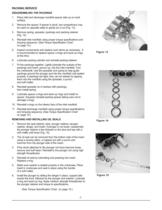
Figure 13 Figure 14 Figure 15 > DISASSEMBLING THE PACKINGS 1.Place inlet and discharge manifold spacer side up on work surface.2.Remove the spacer. If spacer is stuck, two screwdrivers may beused on opposite sides to gently pry it out (Fig. 13).3.Remove spring, spreader, packings and packing retainer(Fig. 14).4. Reinstall inlet manifold using proper torque specifications and torquing sequence. (See Torque Specification Chart on page 10.)5.Inspect components and replace worn items as necessary. It is recommended to replace spacer o-rings and back-up rings at this time.6.Lubricate packing cylinder...
Open the catalog to page 7
PART DESCRIPTIONREF NO.TORQUE Valve Cap **95110 Ft-Lbs Inlet Manifold Bolts 74, 75, 7640 Ft-Lbs Discharge Manifold Bolts **8730 Ft-Lbs Plunger Retainer *2318 Ft-Lbs Rear Cover Bolts5010 Ft-Lbs Bearing Cover Bolts3810 Ft-Lbs Connecting Rod Bolts3232 Ft-Lbs *Use Medium Strength Threadlocker on Assembly** Use Anti-Seize on Assembly > CHECKDAILYWEEKLY50 hrs500 hrs1500 hrs5000 hrs Clean FiltersX Oil LevelX Oil LeaksX Water LeaksX Belts, PulleysX PlumbingX Initial Oil ChangeX Oil Change*X Seal ServiceX Valve ServiceX AccessoriesX >
Open the catalog to page 10
SymptomProbable Cause(s)Corrective Action Pump runs but produces no flow.Pump is not primed.Flood suction, then restart pump. Pump fails to prime.Air is trapped inside pump.Disconnect discharge hose from pump. Flood suction hose, restart pump, and run pump until all air has been evacuated.Pump loses prime.Air leak in suction hose orRemove suction hose and test forChattering noise,inlet fittings.leaks by pressurizing hose with water.Pressure fluctuates.Make sure thread sealant has been used onall fittings.Suction line is blocked, Remove suction line and inspect it for a loosecollapsed or too small.liner...
Open the catalog to page 11
THIS WARRANTYIS EXCLUSIVE. HYPRO MAKES NO OTHER WARRANTY, EXPRESS OR IMPLIED,INCLUDING BUT NOT LIMITED TO ANYWARRANTYOF MERCHANTABILITYOR FITNESS FOR A PARTICULAR PURPOSE. > Hypro warrants to the original purchaser of its products (the PurchaserӔ) that oil crankcase plunger pumps will befree from defects in material and workmanship under normal use for the period of five (5) years, and accessories will be free from defects in material and workmanship under normal use for the period of ninety (90) days. In addition, Hypro warrants to the purchaser all stainless steel pump manifolds will be free...
Open the catalog to page 12All Hypro Pressure Cleaning catalogs and technical brochures
 PRODUCT CATALOG
236 Pages
 Transfer Pumps
7 Pages
 Gear Driven
3 Pages
 Centrifugal Pumps
41 Pages
 9302 Series
2 Pages

Archived catalogs
 DBS & DBA Diaphragm Pump OIPM
20 Pages
 Series 2100 Versa-Twin OIPM
16 Pages
 Hydraulic Pressure Washer OIPM
20 Pages
 Hydraulic Pump Selection Guide
38 Pages
 9302 Series Sales Sheet
2 Pages
 UAS Ceramic Nozzles
2 Pages
 HP Stainless Steel Nozzles
2 Pages
 TwinCap Sales Sheet
2 Pages
 ULD Sales Sheet
2 Pages
 ESI Sales Sheet
2 Pages
 Series 5300 OIPM
20 Pages
 PowerLine Plunger OIPM
24 Pages
 Cleanload OIPM
12 Pages
 Foam Marker OIPM
20 Pages
 Series 5200 Piston Pump OIPM
8 Pages


- Liebherr industrial pump
- Liebherr electric pump
- Liebherr centrifugal pump
- Liebherr self-priming pump
- Liebherr chemical pump
- Liebherr control valve
- Liebherr water valve
- Liebherr transfer pump
- Liebherr diaphragm pump
- Pressure gauge
- Piston pump
- Liebherr pressure regulator
- Hydraulic pump
- Liebherr single-stage pressure regulator
- Liebherr handling pump
- Liebherr cast iron pump
- Liebherr industrial pressure regulator