Rotary Actuators
1 /16Pages

Rotary Actuators
1 /16Pages
Catalog excerpts

DAS ZEICHEN DER HYDROPA GRUPPE DREHANTRIEBE • Betriebsdrücke bis 210 bar • Drehmomente bis 250 000 Nm ROTARY ACTUATORS • Operating pressures up to 210 bar • Torques up to 250 000 Nm Hydropa GmbH & Cie. KG Därmannsbusch 4 • D-58456 Witten Postfach / P.O. Box 31 65 • D-58422 Witten Telefon / Telephone (0 23 02) 70 12-0 Telefax (0 23 02) 70 12-47 Internet: www.hydropa.de • E-Mail: [email protected]
Open the catalog to page 1
Drehantriebe Typ HY-3 SM Rotary actuators type HY-3 SM Die Einsatzgebiete unserer Drehantriebe HY-3 SM liegen im gesamten industriellen Bereich, wie z. B. in Baumaschinen, Werkzeugmaschinen, Biegemaschinen, Gießerei-, Bergbau-, Land- und Verpackungsmaschinen, Transferstraßen, Handhabungstechnik, Armaturen, Schiffsbau, Fahrzeugund Lüftungstechnik, usw. Auf der Grundlage der jahrelangen problemlosen Einsätze basiert die konsequente Weiterentwicklung der in diesem Katalog vorgestellten Baureihe. Neben unseren Drehantrieben sind auf Anfrage auch Dreh-Hub-Kombinationen mit Linearzylindern wahlweise...
Open the catalog to page 2
Drehantriebe Typ HY-3 SM Rotary actuators type HY-3 SM HINTS FOR APPLICATIONS PLANNING An hydraulische Drehantriebe werden die unterschiedlichsten Anforderungen im Hinblick auf Bewegungsablauf, Drehmoment, Positioniergenauigkeit, Halten und Sichern der Position, Abmessungen und Befestigungsarten gestellt. Hierbei können Sie die intensive Beratung durch Techniker der Firma Hydropa oder durch unsere Vertreter und Vertretungen im In- und Ausland heranziehen. Da die Einsatzfälle und Betriebsbedingungen der Anwender recht unterschiedlich sind, kann hier nur auf einige Hauptmerkmale zur richtigen Größenbestimmung...
Open the catalog to page 3
Drehantriebe Typ HY-3 SM Rotary actuators type HY-3 SM DATENBLATT ZUR GRÖSSENBESTIMMUNG UND ZUR GEFAHRENANALYSE DATA SHEET FOR DETERMINING SIZES AND HAZARD ANALYSIS Von From Firma Company Adresse Adress Datum Date Sachbearbeiter Person responsible Projekt Project Telefon Phone Kommission Commission Telefax Fax E-Mail Bedingungen am Einsatzort Conditions at working place Technische Daten Technical data Massenträgheitsmoment Mass Moment of Inertia Hebelarm Leverage Gewicht Weight Radiallast Radial load Separate Lagerung Separate bearing Erforderliche Eigenschaften des Antriebs Necessary feature...
Open the catalog to page 4
Drehantriebe Typ HY-3 SM Rotary actuators type HY-3 SM OPERATING INSTRUCTIONS Die Antriebswelle ist fluchtend zum Gegenstück einzubauen, um eine Überschreitung der zulässigen Axial- und Radialkräfte zu vermeiden. Vor der Inbetriebnahme ist das Hydraulik-System sorgfältig zu reinigen und zu entlüften. The drive shaft is to be aligned properly to the counterpart to avoid exceeding the permissible axial and radial forces. Before commissioning the hydraulic system has to be carefully cleaned and vented. Pressure fluid Empfehlenswert sind Mineralöle der Gruppe HLP nach DIN 51524 Teil 2 und VDMA Blatt...
Open the catalog to page 5
Drehantriebe Typ HY-3 SM Rotary actuators type HY-3 SM FUNCTIONAL DESCRIPTION Der durch die Anschlüsse P1 oder P2 zugeführte Öldruck bewirkt an der Antriebswelle eine Drehbewegung. Dabei wird die Linearbewegung des Kolbens K durch mehrgängige, gegenläufige Steilgewinde an Gehäuse, Kolben und Welle in eine Drehbewegung umgewandelt. The oil pressure which is supplied through connections P1 or P2 causes a rotary movement on the drive shaft. The linear movement of the piston K is converted into a rotary motion by means of multiple helical gears in the housing, piston and shaft. ROTATING DIRECTION...
Open the catalog to page 6
Drehantriebe Typ HY-3 SM Rotary actuators type HY-3 SM TECHNISCHE DATEN TECHNICAL DATA Baugröße / Size max. Nenndrehmoment max. nominal torque a max. Nenndrehmoment bei 210 bar max. nominal torque at 210 bar max. Betriebsdruck max. working pressure max. Radialbelastung max. radial load max. Axialbelastung max. axial load 90° Schluckvolumen bei einem Winkel von Capacity at an angle of Gewicht bei einem Winkel von Weight at an angle of Baugröße / Size max. Nenndrehmoment bei 210 bar max. nominal torque at 210 bar max. Nenndrehmoment max. nominal torque a max. Betriebsdruck max. working pressure...
Open the catalog to page 7
Drehantriebe Typ HY-3 SM Rotary actuators type HY-3 SM ABMESSUNGEN DIMENSIONS Zylindrische Welle (Standard) Cylindrical shaft (standard) Zahnmitte Spline centre Keilwelle (Code “KW”) Spline shaft (Code “KW”) Baugröße / Size ø A k6 ø A m6 DIN 5480 øB ø C f7 D øE øF G H DIN I 6885 J K L M N O P 90° Winkel P 180° Angle P 270° P 360° Q R 90° Winkel R 180° Angle R 270° R 360° S T U Anzahl / Number of U V 9 11 18 14 Zentrierbohrung nach DIN 332 T2, Form D / Centre hole acc. to DIN 332, type D
Open the catalog to page 8
Drehantriebe Typ HY-3 SM Rotary actuators type HY-3 SM ABMESSUNGEN DIMENSIONS Baugröße 80-100 Size 80 up to 100 Baugröße / Size
Open the catalog to page 9
Drehantriebe Typ HY-3 SM Rotary actuators type HY-3 SM FUNCTIONAL DESCRIPTION OF CUSHIONING END POSITIONS Das vom Kolben (c) verdrängte Druckmedium strömt zunächst durch die Anschlussbohrung (b) frei ab, bis der Kolben (c) die Bohrung (b) vollständig verschließt und somit die Kolbengeschwindigkeit drosselt. Nach völliger Überdeckung des Kolbens (c) kann das Medium nur durch die Bohrung (a) entweichen. Die Durchflussmenge von a nach b kann durch die Drosselschraube (d) reguliert werden. Bei Druckeintritt in umgekehrter Richtung strömt das Medium von b nach a. Das Rückschlagventil öffnet sich und...
Open the catalog to page 10
Drehantriebe Typ HY-3 SM Rotary actuators type HY-3 SM SPLINED PROFILE BUSHES Werkstoff C45 (Nachbehandlung durch QPQ-Verfahren) Material: C45 (treated with QPQ-process) Keilnaben-Profilbuchsen nach DIN 5480 auf Anfrage lieferbar Splined profile bushes acc. to DIN 5480 are available on request Baugröße / Size Keilnabenprofil nach DIN 5463 6x11x14 Splineway acc. to DIN 5463 ø A -0,1 B Schnitt A-B Section A-B Nach Montage verstemmen Caulk after installation Stiftlöcher sind angebohrt Pin boles are drilled 100 Baugröße Size Baueinheit Unit KW-Buchse nach DIN 5463 Splined bush acc. to DIN 5463
Open the catalog to page 11All Hydropa catalogs and technical brochures
 Data sheet HYC-Series
20 Pages
 Data sheet HYKS-Series
20 Pages
 Data sheet MPF 100
3 Pages
 Data sheet MPF 030
3 Pages
 Data sheet Accessiors
34 Pages
 Data sheet ZA6RE
1 Page
 Data sheet ZAH6-R
4 Pages
 Data sheet ZN6DMD
1 Page
 Data sheet ZN6DB-VS AB
1 Page
 Data sheet ZN6DB
1 Page
 Data sheet ZN6DR
4 Pages
 Data sheet WE10AH
11 Pages
 Data sheet WE6AH
14 Pages
 Data sheet SPA/SPG pumps
9 Pages
 Datenblatt DS-104 / EX
8 Pages
 Data sheet DS-802
2 Pages
 Datenblatt DS-4*7 / 4*2
10 Pages
 Data sheet DS-507/502
8 Pages
 Data sheet DS-307/302
8 Pages
 Data sheet DS-117/112
8 Pages
 Data sheet HY-3.SM
16 Pages
 Overview special power packs
4 Pages
 Data sheet KA-Power packs
4 Pages
 DS-307 / 302
8 Pages
 DS-507 / 502
8 Pages
 DS-4*7 / 4*2
4 Pages
 DS-802/M/B
2 Pages
 WE 10 AH
11 Pages
 HYDRAULIC CYLINDERS
20 Pages
 DS-117 / DS-112
8 Pages
 2 SPG
2 SPG9 Pages
 ZAH10 DR
1 Page
 WE6AH
WE6AH14 Pages
 DMH-630 R
11 Pages
 Hand pumps
12 Pages
 ZN 6 DBS - * - AB
1 Page
 ZA 6 RE -*
1 Page
 Z 6 R *
1 Page
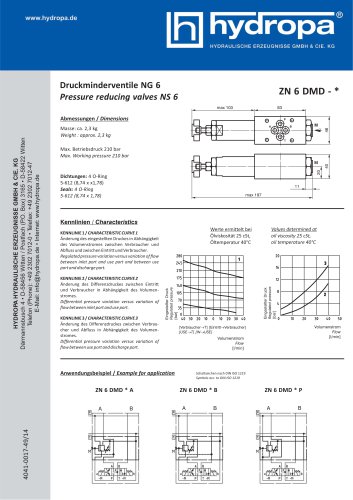
 ZN 6 DMD - *
1 Page
 ZN 6 DB - *
1 Page
 ZN 6 DR-*
4 Pages
 3 SP-B
4 Pages
 2 SP-B
4 Pages
 1 SP-B
4 Pages
 DS-4*7/4*2
4 Pages
 DS-507 / DS-502
8 Pages
 DS-307 / DS-302
8 Pages
 Special - Power Packs
4 Pages
 KOMPAKT-AGGREGATE
4 Pages
 HYDRAULIC MOTORS
16 Pages
 ATEX-PRESSURE SWITCH
1 Page
 SPECIAL POWER PACKS
4 Pages
 MINI POWER PACKS
12 Pages


Archived catalogs
 DS-117/112
8 Pages
- Cylinder
- ERLO linear actuator
- Directional control valve
- Double-acting cylinder
- Hydraulic cylinder
- ERLO pressure switch
- Mechanical pressure switch
- Hydraulic directional control valve
- Single-acting cylinder
- Industrial actuator
- ERLO waterproof pressure switch
- Piston cylinder
- Relief valve
- Spool hydraulic directional control valve
- ERLO adjustable pressure switch
- Liquid pressure switch
- Electrically-operated hydraulic directional control valve
- Double-acting actuator
- ERLO IP65 pressure switch