Catalog excerpts

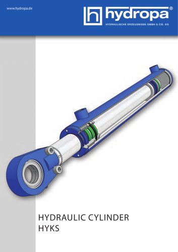
HYDRAULIC CYLINDER HYKS
Open the catalog to page 1
INTRODUCTION The hydraulic cylinder, as a link between hydraulic control and the machine, is suitable for use in many areas of industry, such as pressing and joining applications, the chemical industry or tool making. Hydraulic cylinders can also be used without a problem in areas having extremely high or low ambient temperatures. TABLE OF CONTENTS Page 3 Operating instructions Basis of calculations for hydraulic cylinders The Hydropa HYKS series of hydraulic cylinders exhibit a sturdy welded/bolted construction with honed and seamless cylinder barrels and ground, precision hard...
Open the catalog to page 2
GENERAL GENERAL CHARACTERISTICS Piston diameter: Perm. max. operating pressure: Test pressure: Piston speed: Temperature range: Mounting position: Distance measurement: MATERIALS Piston rod: Cylinder: Seals: 32 to 200 mm 250 bar 350 bar 0.5 m/s to 4 m/s -30° C to +80° C any transducer or inductive proximity switch FILTERING When the system is filled during operation, the hydraulic fluid must be filtered so that contamination with solids does not exceed the thresholds according to NAS 1638 Class 8 (Class 9 for 15μm and smaller) or ISO17/14. Finer filtration increases the lifetime of the...
Open the catalog to page 3
OPERATING INSTRUCTIONS STORAGE In order to ensure a long shelf life of the bearing surfaces and seals of hydraulic cylinders, and to protect them against corrosion, the piston rods should be retracted and the cylinders filled completely with oil. It is important to ensure that no air is trapped in the cylinder and that the connections are sealed airtight. The piston rod thread, the free rod end, and ball and socket joints should be coated lightly with anti-corrosion grease. If the cylinders are stored at fluctuating ambient temperatures, they must be protected with a pressure relief valve...
Open the catalog to page 4
REPLACMENT PARTS When ordering spare parts, always include the imprinted order number, which is located to the right of the base-end connection (in reference to the piston rod). PLEASE NOTE : Installation, repair and commissioning of cylinders may be carried out only by trained specialist personnel with the necessary expertise. Hydropa assumes no liability for any damage resulting from installation, repairs and commissioning, which were not carried out or commissioned by Hydropa. 1 - Piston rod 2 - Cylinder base 3 - Piston 4 - Piston ring 5 - Piston seal 6 - O-ring 7 - Cylinder tube 8 -...
Open the catalog to page 5
BASIS OF CALCULATIONS FOR HYDRAULIC CYLINDERS Piston and ring surfaces / lifting and tractive forces Piston Ø (mm) 32 40 50 63 80 100 125 140 160 180 200 Theoretical compressive force at 210 bar (kN) 16,89 26,39 EFFICIENCY FACTOR The values given in the table do not take into account the efficiency factor. Every hydraulic cylinder loses power due to the friction resistance of the sealing and guiding elements. Since the effect of these losses is different at different pressures, the following average values are anticipated as the efficiency factors: Efficiency factor Pressure (bar)
Open the catalog to page 6
PISTON FORCES PISTON SPEED p = pressure A = effective piston surface F = effective piston force d1 = piston diameter d2 = piston rod diameter μ = efficiency factor of the cylinder Q = volumetric flow rate A = effective piston surface v = piston speed Effective piston force: F=p*A*μ Piston speed: v=Q/A given: Hydraulic cylinder with d1 = 100 mm, d2 = 70 mm, μ = 0.85, p = 60 bar [ 1 bar = 10 N/cm2 ] given: Hydraulic cylinder with d1 = 50 mm, d2 = 36 mm, Q = 12 l/min needed: Effective piston force (F) needed: Piston speed (v) retraction: retraction: F=p*A*μ = 600 N/cm2 * ( π * ( ( 10 cm )2 - (...
Open the catalog to page 7
TECHNICAL DATA Buckling calculation The tables show the permissible stroke in mm at buckling stress (compressive stress) according to Euler with 3.5 times the safety factor and flexibly guided load. The calculation of buckling SK is carried out according to Euler, whereby in simplified terms the piston rod and tube can be regarded as a slender rod. Euler case 3 using head flange as an example = modulus of elasticity 2,1 * 105 for steel in N/mm2 = moment of area im mm4 4 d *π for circular cross-section = 64 Euler case 2 using articulated / swivel eye as an example Mounting type articulated /...
Open the catalog to page 8
Mounting type head flange HYKS-...-K-... (with measurement “D” and piston rod eye) Piston Ø (mm) Piston rod Ø (mm) Mounting type base flange HYKS-...-B-... (with measurement “J” and piston rod eye) Piston Ø (mm) Piston rod Ø (mm) Mounting type tangential feet HYKS-...-T-... (with measurement “P” and piston rod eye) Piston Ø (mm) Piston rod Ø (mm)
Open the catalog to page 9
MOUNTING METHODS Optional: Piston rod eye, fork head We also build other models according to customer specifications. basic cylinder HYKS-... articulated eye, base e e end HYKS-...-G-... base flange HYKS-...-B-... head flange HYKS-...-K-... trunnion HYKS-...-M-... swivel eye, base end end HYKS-...-S-... tangential feet HYKS-...-T-... HYKS ... T ...
Open the catalog to page 10
PRODUCT KEY HYDRAULIC CYLINDER SERIES: HYKS 8 TYPE OF MOUNTING ON PISTON ROD G = piston rod eye, clampable S = swivel eye, clampable GK = fork head, clampable X = custom mounts 1 TYPE D = double-acting E = single-acting 2 MOUNTING TYPE G = articulated eye S = swivel eye K = head flange B = base flange M = trunnion T = tangential feet 9 POSITION OF THE OIL PORTS (with reference to the rod) 0 = oil port position standard 1 = oil port position 90° to the left 2 = oil port position 90° to the right 3 = oil port position 180° 4 = custom position see SO-text 3 PISTON DIAMETER (mm) 4 ROD DIAMETER...
Open the catalog to page 11
DIFFERENTIAL CYLINDER WITH ARTICULATED / SWIVEL EYE Differential cylinder with articulated / swivel eye Type W-Tube (Standard) Tilt GIHR-K, PH11 angle SA-K, GK Ø α (equipm.)
Open the catalog to page 12
DIFFERENTIAL CYLINDER WITH BASE FLANGE Differential cylinder with base flange Type Weight (kg) GIHR-K, each SA-K, GK for stroke 100mm (equipm.) 0mm of stroke 0,7 20 2,5 0,8 0,9 25 3,5 1 W-Tube (Standard)
Open the catalog to page 13All Hydropa catalogs and technical brochures
-
Data sheet HYC-Series
20 Pages
-
Data sheet HYKS-Series
20 Pages
-
Data sheet MPF 100
3 Pages
-
Data sheet MPF 030
3 Pages
-
Data sheet Accessiors
34 Pages
-
Data sheet ZA6RE
1 Pages
-
Data sheet ZAH6-R
4 Pages
-
Data sheet ZN6DMD
1 Pages
-
Data sheet ZN6DB-VS AB
1 Pages
-
Data sheet ZN6DB-VS A/B/P
1 Pages
-
Data sheet ZN6DB
1 Pages
-
Data sheet ZN6DR
4 Pages
-
Data sheet WE10AH
11 Pages
-
Data sheet WE6AH
14 Pages
-
Data sheet SPA/SPG pumps
9 Pages
-
Datenblatt DS-104 / EX
8 Pages
-
Data sheet DS-802
2 Pages
-
Datenblatt DS-4*7 / 4*2
10 Pages
-
Data sheet DS-507/502
8 Pages
-
Data sheet DS-307/302
8 Pages
-
Data sheet DS-117/112
8 Pages
-
Data sheet HY-3.SM
16 Pages
-
Overview special power packs
4 Pages
-
Data sheet KA-Power packs
4 Pages
-
DS-307 / 302
8 Pages
-
DS-507 / 502
8 Pages
-
DS-4*7 / 4*2
4 Pages
-
WE 10 AH
11 Pages
-
DS-117 / DS-112
8 Pages
-
2 SPG
9 Pages
-
ZAH10 DR
1 Pages
-
WE6AH
14 Pages
-
DMH-630 R
11 Pages
-
Hand pumps
12 Pages
-
ZN 6 DBS - * - AB
1 Pages
-
ZA 6 RE -*
1 Pages
-
Z 6 R *
1 Pages
-
ZN 6 DMD - *
1 Pages
-
ZN 6 DB - *
1 Pages
-
ZN 6 DR-*
4 Pages
-
3 SP-B
4 Pages
-
2 SP-B
4 Pages
-
1 SP-B
4 Pages
-
DS-802/M/B
2 Pages
-
DS-4*7/4*2
4 Pages
-
DS-507 / DS-502
8 Pages
-
DS-307 / DS-302
8 Pages
-
Special - Power Packs
4 Pages
-
KOMPAKT-AGGREGATE
4 Pages
-
HYDRAULIC MOTORS
16 Pages
-
ATEX-PRESSURE SWITCH
1 Pages
-
SPECIAL POWER PACKS
4 Pages
-
MINI POWER PACKS
12 Pages
Archived catalogs
-
DS-117/112
8 Pages
-
Rotary Actuators
16 Pages


