

Data sheet ZN6DR

Data sheet ZN6DR
Catalog excerpts
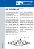
Zwischenplatten - Drosselrückschlagventile NG 6 Modular throttle check valves NS 6 FUNCTIONAL DESCRIPTION Zwillings-Drosselrückschlagventile dienen zur Drosselung der Volumenströme in zwei getrennten Leitungen (A, B) eines hydraulischen Kreises. Di e Modulbauweise ermöglicht sechs Schaltmöglichkeiten. Die Drossel-Rückschlagventile sind in die Kanäle A oder B oder in A und B eingebaut. Sie begrenzen den Durchfluss in einer Richtung und gestatten freien Rücklauf in der Gegenrichtung. Der Drosselkolben (2) wird mittels einer Verstellschraube (3) verschoben, wodurch eine Veränderung des Durchflussquerschnitts erzielt wird. Eine Linksdrehung der Drosselschraube bewirkt eine Erhöhung des Durchflusses, eine Rechtsdrehung bewirkt eine Verminderung des Durchflusses. Die durch Kanal A1 zugeführte Druckflüssigkeit gelangt durch die Drosselkerbe und Kreisringfläche zum Anschluss A2. Die vom Kanal B2 zurückfließende Druckflüssigkeit verschiebt den Ventilsitz (4) gegen die Feder (5) in Richtung des Drossel-kolbens und ermöglicht dadurch den ungehinderten Durchfluss zu Anschluss B1 (Funktion des Rückschlagventils). Die Zwischenplatten-Bauweise ermöglicht eine einfache Verbindung mit anderen Steuerelementen derselben Nenngröße in einer Höhenverkettung. Die Dichtung des Ventils in der Verbindungsfläche erfolgt durch ein Zwischenblech (6) mit eingebauten Square-Ringen. Je nach Einbaulage des Ventils kann der Drosseleffekt im Zulauf oder im Ablauf erfolgen. Der Umbau von Zulauf- in Ablaufregelung erfolgt durch Drehen des Ventils um 180° um die Horizontalachse. Die Anordnung des Drosselrückschlagventils entspricht der schematischen Darstellung auf dem Typenschild. Die Betätigung der Verstellschraube erfolgt mittels eines Schlüssels oder einen Drehknopf. Die Oberfläche des Ventilgehäuses ist phosphatiert, alle anderen Teile sind verzinkt. Double throttle valves are used to control flow rates in two separate lines (A, B) of a hydraulic circuit. The sandwich plate design provides six functional symbols. The throttle valve is built into channel A or B or into channels A and B. The valve restricts the fluid flow in one direction while providing reverse free-flow in the opposite direction. Adjusting the throttling spool (2) by means of a set screw (3) generates a change in the cross section of passage. Anticlockwise rotation causes an increase of flow, clockwise rotation causes a decrease of flow. Fluid entering port A1 is throttled to port A2 via a groove and an annulus area. Fluid returning from port B2 shifts the valve seat (4) against the spring (5), thus creating a passage which allows reverse free-flow to port B1 (function as a check valve).The sandwich design enables simple stacking with other com-ponents of the same size. The separate O-ring plate (6) with fitted O-rings provides sealing of the valve connecting surface. According to the valve arrangement, the meter-in or meter-out control is provided. Changing the meter-in mode into the meter-out mode can be done by turning the valve by 180° around its horizontal axis. The orientation of the throttle check valves in the valve body corresponds with the symbols shown on the name plate. The set screw can be operated by a key or a hand knob. The valve housing is phosphate coated, the surfaces of the other parts are zinc coated.
Open the catalog to page 1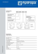
TYPENSCHLUSSEL TYPE CODE ZN Zwischenplattenventil Modular valve NenngroBe 6 Nominal size 6 Drosselruckschlagventil Throttle check valve Einstellelement Adjustment element KENNGROSSEN CHARACTERISTICS 4041-0009-13/10-2/4 Max. Volumenstrom Max. Flow
Open the catalog to page 2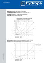
KENNLINIEN (gemessen bei n=35 mm²/s und t=40° C) CHARACTERISTIC CURVES (measured at n=35 mm²/s and t=40° C) Drosselventil (Abhängigkeit der Druckdifferenz vom Volumenstrom) Throttle valve (Pressure difference related to flow) Druckdifferenz [bar] Pressure difference [bar] Drosseleinstellung in Umdrehungen (vom Anschlag) Throttle setting in turns (from the end stop) Volumenstrom Q [l/min] Volume flow Q [l/min] Rückschlagventil (Druckdifferenz bei Durchflussrichtung von A2 zu A1 (von B2 zu B1) Check valve (Pressure difference related to flow from A2 to A1 (from B2 to B1) Drosselventil geschlossen...
Open the catalog to page 3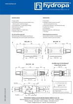
1 Typenschild 2 Verstellschraube mit Innensechskant 5 mm, Kontermutter und Schutzkappe 3 Verstellelement - Drehknopf mit Skala 4 Kontermutter, SW 10 5 Zwischenplatte 6 Square-Ring 9,25 x 1,68 (4 Stck.) 7 Verschlussschraube 1 Type plate 2 Hexagon socket screw 5 mm with lock nut and protection cap 3 Adjustment element - hand knob with scale 4 Locknut hex. 10 mm 5 O-Ring plate 6 Square ring 9,25 x 1,68 (4 pieces) 7 Hex plug Für alle Ausführungen gilt: Rechtsdrehung: Erhöhung des Durchflusses Linksdrehung: Verminderung des Durchflusses With all adjustment elements: Anticlockwise rotation: increase...
Open the catalog to page 4All Hydropa catalogs and technical brochures
 Data sheet HYC-Series
20 Pages
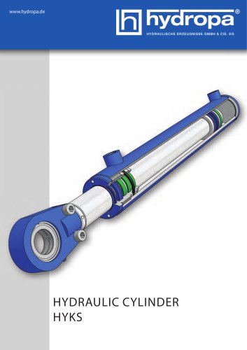 Data sheet HYKS-Series
20 Pages
 Data sheet MPF 100
3 Pages
 Data sheet MPF 030
3 Pages
 Data sheet Accessiors
34 Pages
 Data sheet ZA6RE
1 Page
 Data sheet ZAH6-R
4 Pages
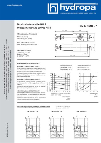 Data sheet ZN6DMD
1 Page
 Data sheet ZN6DB-VS AB
1 Page
 Data sheet ZN6DB
1 Page
 Data sheet WE10AH
11 Pages
 Data sheet WE6AH
14 Pages
 Data sheet SPA/SPG pumps
9 Pages
 Datenblatt DS-104 / EX
8 Pages
 Data sheet DS-802
2 Pages
 Datenblatt DS-4*7 / 4*2
10 Pages
 Data sheet DS-507/502
8 Pages
 Data sheet DS-307/302
8 Pages
 Data sheet DS-117/112
8 Pages
 Data sheet HY-3.SM
16 Pages
 Overview special power packs
4 Pages
 Data sheet KA-Power packs
4 Pages
 DS-307 / 302
8 Pages
 DS-507 / 502
8 Pages
 DS-4*7 / 4*2
4 Pages
 DS-802/M/B
2 Pages
 WE 10 AH
11 Pages
 HYDRAULIC CYLINDERS
20 Pages
 DS-117 / DS-112
8 Pages
 2 SPG
2 SPG9 Pages
 ZAH10 DR
1 Page
 WE6AH
WE6AH14 Pages
 DMH-630 R
11 Pages
 Hand pumps
12 Pages
 ZN 6 DBS - * - AB
1 Page
 ZA 6 RE -*
1 Page
 Z 6 R *
1 Page
 ZN 6 DMD - *
1 Page
 ZN 6 DB - *
1 Page
 ZN 6 DR-*
4 Pages
 3 SP-B
4 Pages
 2 SP-B
4 Pages
 1 SP-B
4 Pages
 DS-4*7/4*2
4 Pages
 DS-507 / DS-502
8 Pages
 DS-307 / DS-302
8 Pages
 Special - Power Packs
4 Pages
 KOMPAKT-AGGREGATE
4 Pages
 HYDRAULIC MOTORS
16 Pages
 ATEX-PRESSURE SWITCH
1 Page
 SPECIAL POWER PACKS
4 Pages
 MINI POWER PACKS
12 Pages


Archived catalogs
 DS-117/112
8 Pages
 Rotary Actuators
16 Pages
- Cylinder
- Actuator
- Linear actuator
- Directional control valve
- Double-acting cylinder
- Hydraulic cylinder
- Pressure switch
- Hydraulic directional control valve
- Mechanical pressure switch
- Waterproof pressure switch
- Single-acting cylinder
- Piston cylinder
- Spool hydraulic directional control valve
- Industrial actuator
- Relief valve
- Adjustable pressure switch
- Liquid pressure switch
- Electrically-operated hydraulic directional control valve
- Double-acting actuator
- IP65 pressure switch