Catalog excerpts
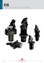
CG LINK CLAMP CYLINDERS
Open the catalog to page 1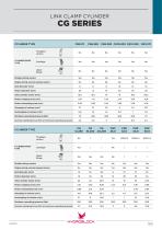
LINK CLAMP CYLINDER
Open the catalog to page 2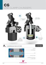
CG LINK CLAMP CYLINDERS VCS10 unclampimg control valve (upon request) Metal wiper (upon request) Flow control valve (upon request) COMPENSATION SYSTEM LEVER CUP SPRING ELASTIC RING COMPENSATION DISK CLAMP ARM
Open the catalog to page 3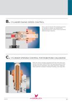
B. CYLINDER SWING SPEED CONTROL Flow control valve for the clamping process. All standard cylinders are prepared for retrofitting the flow control valve (accessory delivered upon request). C. CYLINDER OPENING CONTROL FOR ROBOTIZED UNLOADING With link clamp cylinders equipped with the VCS clamp arm control valve (e.g. CG12.70 FDV), the opening position of the cylinder can be monitored, which gives maximum safety for robot-assisted workpiece loading/unloading. (see page 163)
Open the catalog to page 4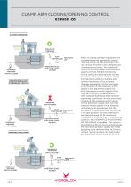
CLAMP ARM CLOSING/OPENING CONTROL SERIES CG CLAMPED WORKPIECE O PNEUMATIC PRESSURE SWITCH CLOSED FLOW PNEUMATIC CONTROLLER LINE HYDRAULIC PRESSURE SWITCH CLOSED PRESSURE GAUGE FOR VISUAL CHECK 0-12 BAR WORKPIECE RELEASED/ INTERMEDIATE POSITION X PRESSURE SWITCH OPEN FLOW PNEUMATIC CONTROLLER LINE HYDRAULIC PRESSURE SWITCH CLOSED PRESSURE GAUGE FOR VISUAL CHECK 0-12 BAR WORKPIECE UNCLAMPED With link clamp cylinders equipped with a single integrated pneumatic supply channel, closing of the pneumatic line can only be ensured in the clamping and unclamping positions. The combined control of...
Open the catalog to page 5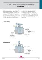
CLAMP ARM CLOSING/OPENING CONTROL SERIES CG With link clamp cylinders equipped with the VCS clamp arm control valve (e.g. CG12.70 FDV), the opening position of the cylinder can be monitored, which gives maximum safety for robot-assisted workpiece loading/unloading. Considering the cylinder type used, clamping of the workpiece can be monitored by the pressure switch of the hydraulic clamping line. With CG link clamp cylinders from HYDROBLOCK, clamping is ALWAYS performed using the large cylinder area and there is no risk of accidental opening of the pressurized cylinder. On the other hand,...
Open the catalog to page 6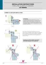
INSTALLATION INSTRUCTIONS FOR LINK CLAMP CYLINDERS CG SERIES CORRECT CLAMP ARM INSTALLATION ATTENTION: For special application requirements, it is also possible to use the clamp arm in a laterally off-set position relative to the cylinder. In this case, the operating pressures specified in the diagrams MUST be reduced. Please contact HYDROBLOCK for more detailed information. L The clamp arm should be dimensioned such as to ensure that it is arranged at right angles to the clamping point. In addition, the arm must be aligned in parallel to the surface of the clamped workpiece, as otherwise...
Open the catalog to page 7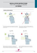
If the workpiece needs to be clamped on an inclined If the cylinder is installed at a different angle, the surface, the cylinder must be installed at right angles clamping forces would produce reaction forces that to the surface. could damage the cylinder. Please observe the clamping arm lengths and the fields of application specified in the catalogue. Whereas extremely long clamping arms could affect correct workpiece removal, very short clamping arms could lead to premature wear or damage to the cylinder.
Open the catalog to page 8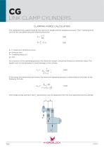
CG LINK CLAMP CYLINDERS CLAMPING FORCE CALCULATION The clamping force is determined by the clamp arm length and the operating pressure. The F clamping force can thus be calculated using the following formulas: k, l = Clamp arm dimensions [mm] p = Pressure [bar] S = Clamping area [cm2] = 0.9 As a function of the operating pressure, the clamp arm length l should be limited to a minimum value. This length must not be exceeded to avoid damage to the cylinder. If the clamp arm dimensions are known, the maximum operating pressure is determined on the basis of the following formula: With...
Open the catalog to page 9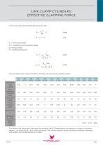
In this case, the following formulas must be used: Fm = Spring force [kN] k, l = Clamping arm dimensions [mm] p = Pressure [bar] S = Clamping area [cm2] The constants to be used in the above formulas are specified in the table below: The shorter the clamp arm, the longer the reaction time R. Depending on the pressure p, there is a minimum length l at which the R limit value is reached. The cylinder-specific clamping force for different clamping arm lengths can be represented in a graph.
Open the catalog to page 10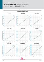
ICG SERIES DOUBLE ACTING . EFFECTIVE CLAMPING FORCE CG8.250 CG8.200 Effective clamping force (kN) Effective clamping force (kN) Effective clamping force (kN)
Open the catalog to page 11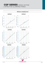
CGF SERIES SINGLE ACTING EFFECTIVE CLAMPING FORCE Effective clamping force CGF26.0 CGF32.0 6,0 Effective clamping force (kN) Effective clamping force (kN) 7,0 Effective clamping force (kN) Effective clamping force (kN) CGF50S Effective clamping force (kN) Effective clamping force (kN)
Open the catalog to page 12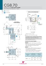
CG8.70 DOUBLE-ACTING LINK CLAMP CYLINDER MAX. OPERATING PRESSURE = 70BAR : Clamping : Unclamping INSTALLATION DIMENSIONS METAL WIPER AS STANDARD EQUIPMENT ◊ Piston contact surface Debur and round off any edges CYLINDER WITHOUT COMPENSATION SYSTEM If the clamp arm clearance needs to be compensated, please order the CG8.70V version with compensated clamp arm. EFFECTIVE PISTON AREA Included in the scope of supply: • Mounting screws M5x16 DIN 912/12.9 grade. Material: • Piston/rod/bolts: Case-hardened steel, ground. • Body: Free machining steel, nitrocarburized. • Lever: Quenched and Tempered...
Open the catalog to page 15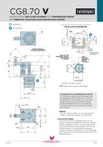
CG8.70 V DOUBLE-ACTING LINK CLAMP CYLINDER WITH COMPENSATION SYSTEM AND PNEUMATIC VALVE FOR CLAMP ARM POSITION CONTROL : Clamping : Unclamping INSTALLATION DIMENSIONS METAL WIPER AS STANDARD EQUIPMENT AREA OF THE PNEUMATIC SUPPLY PORT OF THE CYLINDER BORE FOR THE PNEUMATIC SUPPLY (EXAMPLE) ◊ Piston contact surface Options: • The link clamp cylinder can also be ordered without clamp arm (order no. CG8.70VN). Debur and round off any edges CYLINDER WITH COMPENSATION SYSTEM If, for technical reasons, special clamps arms are manufactured in-house by the customer, HYDROBLOCK will be ready to...
Open the catalog to page 16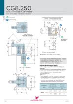
CG8.250 DOUBLE-ACTING LINK CLAMP CYLINDER MAX. OPERATING PRESSURE = 250BAR : Clamping : Unclamping METAL WIPER AS STANDARD EQUIPMENT 6 MIN. Debur and round off any edges CYLINDER WITHOUT COMPENSATION SYSTEM If the clamp arm clearance needs to be compensated, please order the CG8.250V version with compensated clamp arm. Included in the scope of supply: • Mounting screws M5x16 DIN 912/12.9 grade Material: • Piston/rod/bolts: Case-hardened steel, ground. • Body: Free machining steel, nitrocarburized. • Lever: Quenched and Tempered steel. • Clamp arm: C45. Options: • Upon request, different...
Open the catalog to page 17All HYDROBLOCK catalogs and technical brochures
-
HPC
2 Pages
-
CT PULL/PUSH CYLINDERS
21 Pages


