- Catalogs
- Hydro-Vacuum
- Deep-well pumps
Deep-well pumps
1 /94Pages

Deep-well pumps
1 /94Pages
Catalog excerpts

Deep-well pumps
Open the catalog to page 1
www.hv.pl [email protected]
Open the catalog to page 2
GENERAL DATA Application Deep-well units are designed for use in water supply systems, for pumping and increasing liquid pressures in technological processes, reduction of ground water level, watering systems, and other industrial and residential applications. Essential advantages of type G deep-well pumps • • • • • • • • • • • the pump unit may be installed in a suspended, standing or horizontal position without necessity to rebuild foundations may be installed in drilled, small-diameter wells without suction jackets may be installed in drilled, large-diameter wells and in large tanks, with...
Open the catalog to page 3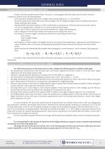
GENERAL DATA Cooperation with frequency converters All deep-well units manufactured by Hydro-Vacuum S.A. and equipped with three-phase electric motors may have a frequency converter drive. Recommendations: • avoid operation of submersible motors at higher than nominal frequencies, i.e. 50 and 60 Hz; • the power rating of the submersible motor selected ought to be one magnitude higher than the standard motor power rating, matching a given pump; • the permissible minimum frequency is 32Hz, provided that a minimum rate of flow past the external motor surface of 0.2 m/s is maintained; it is advised...
Open the catalog to page 4
GENERAL DATA Constructional executions Specific configurations are marked by sub-codes comprising the symbols - e1 e2 e3 e4 , wherein: e1 - denotes the type of connection to the motor e3 - denotes the type of outlet e2 - denotes the type or absence of valve e4 - is reserve (the symbol 0) Explanation of the sub-code structure: e1 Constructional execution designation Pump type/design variant Execution type Pump to a NEMA 4” shaft end motor 1 Pump to a NEMA 6” shaft end motor Pump to a NEMA 4” shaft end motor Pump to a NEMA 6” shaft end motor Pump to a NEMA 8” shaft end motor 3* Pump to a NEMA 8”...
Open the catalog to page 6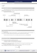
Product finish (protective coatings} 1 - standard 2 - special All essential information about the pump is encoded in its designation. The function of the designation, provided both in this catalogue and on the pump data plate, is to help make the right choice of a product and to keep in touch with us during its operation, for instance, when ordering spare parts. The product code is structured as follows: constructional execution (see: Constructional execution) pump type material execution scope of delivery (see: Scope of delivery) type dimensions number of stages (all pumps except GFB.1) pump...
Open the catalog to page 7
GENERAL DATA Selection of feeder cables For temperatures above +25°C, the selected feeder cable cross-section should be adjusted with regard to the cable current load limit, based on tolerable current loads given in Tables 1 and 2. Example Select a feeder cable cross-section for a direct starting motor given the following parameters: - supply voltage rating, Un, = 400 V, - current rating: 40 A, - required cable length: 300 m, - ambient temperature t = +450C. From Diagram 1 select the cable cross-section 35 mm2 for 40 A current rating and 300 m cable length. For such cable cross-section at 40...
Open the catalog to page 8
Voltage drop 3%; ambient temperature 25°C; cos 0 = 0,85. @ HYDRO-VACUUM®s a ul. Droga Jeziorna 8, 86-303 Grudzi^dz, Polska www.hv.pl
Open the catalog to page 9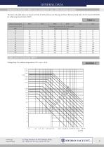
The data in the table below are based on Order 29 of the Ministry of Mining and Power Industry dated July 17th 1974, and VDE 0298 for cable temperature limit of 60oC. TABLE 2 Voltage drop 3%; ambient temperature 25oC; cos 0 = 0,85. www.hv.pl [email protected]
Open the catalog to page 10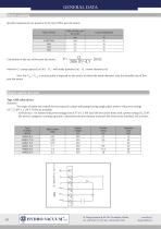
Motor coolin Specific requirements are posed as to the rate of flow past the motor: ul. Droga Jeziorna 8, 86-303 Grudzi^dz, Polska www.hv.pl
Open the catalog to page 11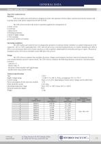
Motor safety devices UZS 4 3 x 400 V (3 x 380 V), 50 Hz, arrangement TN-C-S, TN-S from 1,2 A to 20 A (depending on motor power rating), use the table below 4 VA 6 mA max. from -10°C to +40°C (from-30°C to +40°C) IP65 1,5 kg Type UZS 4 safety devices Function UZS 4 are safety and control devices, designed to protect the operation of three-phase asynchronous electric motors used in pump units, at the power output from 0.55 kW to 9 kW. The UZS 4 device protects the motor in operation against the consequences of: e) drop of supply voltage, g) excessive number of switches. Operating conditions The...
Open the catalog to page 12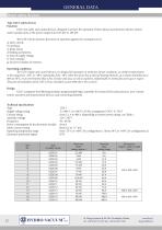
Motor safety devices Type UZS 5 safety devices Function UZS 5 are safety and control devices, designed to protect the operation of three-phase asynchronous electric motors used in pump units, at the power output from 0.55 kW to 185 kW The UZS 5 device protects the motor in operation against the consequences of: e) drop of supply voltage, g) excessive number of switches. Operating conditions The UZS 5 safety-and-control devices are designed for operation in moderate climate conditions, at ambient temperatures in the range from -10°C to +40°C (optionally, from -30°C when the device has a internal...
Open the catalog to page 13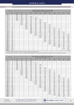
Head loss Flow rate The pressure loss data above are specified for a 100 m straight section of pipework. For elbows, T-pipes, non-return valves or cut-off gate valves, a length of 5 m is added to the straight section of pipework for each of the above elements.
Open the catalog to page 14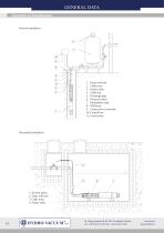
GENERAL DATA Examples of installations Vertical installation 1. Deep-well unit 2. Cable joint 3. Feeder cable 4. Cable clip 5. Discharge pipe 6. Pressure switch 7. Hydrophore tank 8. Well head 9. Connection to network 10. Control box 11. Level sensor Horizontal installation 1. Suction jacket 2. Deep-well unit 3. Cable joint 4. Feeder cable www.hv.pl [email protected]
Open the catalog to page 15
GENERAL DATA Alternative deep-well unit installations direct horizontal installation by-pass horizontal installation by-pass vertical installation direct vertical installation deep-well unit in leak-proof jacket – horizontal installation - www.hv.pl [email protected]
Open the catalog to page 16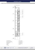
GENERAL DATA Pump design GAB.2, GAB.4, GAB.5 1. Discharge casing 2. Non-return valve head 3. Non-return valve housing 4. Bearing housing 5. Pump shaft 6. Impeller 7. Stator 8. Coupling 9. Suction casing 10. Feeder cable 11. Connecting band 12. Middle casing 13. Cable duct 14. Perforated sheet 15. Motor www.hv.pl [email protected]
Open the catalog to page 17All Hydro-Vacuum catalogs and technical brochures
 LCA pressure switches
2 Pages
 Self-priming pumps
84 Pages


