- Catalogs
- HYDRO LEDUC
- MA series hydraulic motors | SAE version
MA series hydraulic motors | SAE version
1 /16Pages

MA series hydraulic motors | SAE version
1 /16Pages
Catalog excerpts

CHARACTERISTICS OF THE MA SERIES MOTORS (SAE) Motor model Theoretical maximal power at 5800 psi 400 bar Max. allowable pressure continuous / peak psi (1) For higher speeds, please contact us. ►Acceptable forces applied to motor shaft Motor model N/psi (N/bar) * Fr: radial force measured at mid point of length of shaft. Fa: axial force which tends to push the shaft inwards. * Differential pressure between A and B. For other forces, please contact us.
Open the catalog to page 1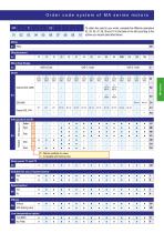
Order code system of MA series motors MA To obtain the code for your motor, complete the different parameters 02, 04, 05, 07, 08, 09 and 10 in the table on the left according to the options you require (see table below). Mounting flange SAE B 2 bolts 0 = Without suitability for valves 1 = Compatible with flushing valve Drain ports T1 and T2 2 Suitable for use of speed sensor 07
Open the catalog to page 2
Cylindrical keyed shaft Ø 1 ″ Dimensions in inches (mm) are given only as an indication.
Open the catalog to page 3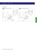
►Inlet ports Side threaded ports A and B Rear threaded ports A and B Dimensions in inches (mm) are given only as an indication.
Open the catalog to page 4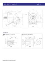
Cylindrical keyed shaft Ø 1¼″ Dimensions in inches (mm) are given only as an indication.
Open the catalog to page 5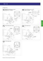
Side SAE flange ports A and B SAE 1/2″ 6000 psi Rear SAE flange ports A and B SAE1/2″ 6000 psi Ø 0.43 (11) Rear threaded ports A and B Side threaded ports Side threaded ports Dimensions in inches (mm) are given only as an indica
Open the catalog to page 6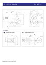
Cylindrical keyed shaft Ø 1¼″ Dimensions in inches (mm) are given only as an indication.
Open the catalog to page 7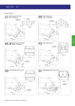
MA 32 - 41 ►Inlet ports SAE flange ports, bottom SAE 1/2″ 6000 psi Rear flange ports SAE 1/2″ 6000 psi Side flange ports A and B SAE 1/2″ 6000 psi Rear threaded ports 15/16"-12UN-2B depth 0.79 (20) Side threaded ports A and B Side threaded ports A and B + valve Dimensions in inches (mm) are given only as an indication.
Open the catalog to page 8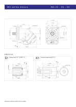
Cylindrical keyed shaft Ø 1¼″ Dimensions in inches (mm) are given only as an indication.
Open the catalog to page 9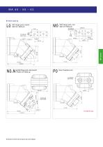
►Inlet ports SAE flange ports, bottom SAE 3/4″ 6000 psi 2 (50.8) SAE flange ports, rear SAE 3/4″ 6000 psi SAE flange ports, side A and B SAE 3/4″ 6000 psi Rear threaded ports Dimensions in inches (mm) are given only as an indication.
Open the catalog to page 10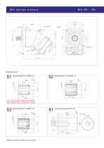
Dimensions in inches (mm) are given only as an indication.
Open the catalog to page 11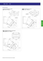
SAE flange ports, bottom SAE 1″ 6000 psi 2.25 (57.2) 1.09 (27.8) SAE flange ports, rear SAE 1″ 6000 psi SAE flange ports, side A and B SAE 1 ″ 6000 psi Dimensions in inches (mm) are given only as an indication.
Open the catalog to page 12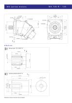
Cylindrical keyed shaft Ø 1¾″ Dimensions in inches (mm) are given only as an indication.
Open the catalog to page 13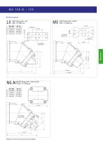
SAE flange ports, rear SAE 1¼″ 6000 psi MA 125 SAE flange ports, bottom SAE 1¼″ 6000 psi SAE flange ports, side A and B SAE 1¼″ 6000 psi Dimensions in inches (mm) are given only as an indication.
Open the catalog to page 14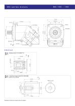
Cylindrical keyed shaft Ø 50 DIN 6885 AS 14 x 9 x 70 mm Dimensions in inches (mm) are given only a
Open the catalog to page 15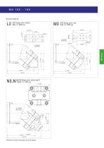
SAE flange ports, bottom SAE 1¼″ 6000 psi SAE flange ports, rear SAE 1¼ ″ 6000 psi 7.64 (194) SAE flange ports, side A and B ″ Dimensions in inches (mm) are given only as an indication.
Open the catalog to page 16All HYDRO LEDUC catalogs and technical brochures
 AP (L) piston accumulators
6 Pages
 ABVE bladder accumulators
4 Pages
 AS spherical accumulators
4 Pages
 Customized products
8 Pages
 XRT6868 twin flow pump
1 Page
 MT45 series motors
2 Pages
 M series hydraulic motors
16 Pages
 Powerpack GEP 7.3
2 Pages
 PA / PAC series pumps
6 Pages
 TXV series pumps
10 Pages
 Microhydraulics
24 Pages
 Hydropneumatic accumulators
36 Pages
 Piston pumps for trucks
48 Pages


- Hydraulic pump
- Hydraulic piston pump
- Hydraulic motor
- Compact hydraulic pump
- High-pressure hydraulic pump
- Piston hydraulic motor
- Standard hydraulic pump
- Fixed-displacement hydraulic motor
- Variable-displacement hydraulic pump
- Rugged hydraulic pump
- Gear hydraulic motor
- High-speed hydraulic pump
- Vehicle hydraulic pump
- Compact hydraulic motor
- High-pressure hydraulic motor
- Double hydraulic pump
- Fixed-displacement hydraulic pump
- Hydraulic screw pump
- Open circuit hydraulic motor
- Variable-displacement hydraulic motor