
- Catalogs
- HYDRO LEDUC
- Bent axis hydraulic motors - Fixed displacement

Bent axis hydraulic motors - Fixed displacement

Bent axis hydraulic motors - Fixed displacement
Hydraulic motors are crucial in applications requiring high torque in compact spaces, such as mowers, blowers, and industrial winches. They are particularly useful where mechanical solutions are complex or where electrical/pneumatic power is unavailable. Efficiency is illustrated through a graph showing global and volumetric efficiency against pressure.
Hydraulic motors convert hydraulic flow into rotational speed and pressure into torque. LEDUC motors are distinguished by their high-quality materials, increased bearing capacity, reinforced seals, and a design that minimizes friction and noise.
Motors must be pre-filled with oil and are designed for mineral-based hydraulic fluids. The recommended viscosity range is 15 to 400 cSt. They can operate in all positions, adhering to specific temperature and pressure guidelines.
Selection involves considering torque, speed, and flow requirements, with calculations based on displacement, pressure difference, and efficiency. Technical assistance is available for motor selection.
Ensure motors are filled with hydraulic fluid before start-up. Follow guidelines for drain pressure and rotation direction to prevent operational issues.
The M series features motors with displacements from 5 to 180 cc/rev, suitable for various applications. Specifications include continuous and intermittent speeds, torque, and pressure limits.
Motor codes are based on parameters such as displacement, mounting flange, shaft type, and inlet ports. Options include speed sensors and flushing valves.
Dimensions for M series motors are provided, detailing shaft and port specifications.
Detailed specifications for motor models in the M, MA, and MSI series include dimensions, shaft types, and pressure ratings, with measurements in inches and millimeters.
Different motor models like MA 45, MA 80, MA 108R, and MSI series are outlined, each with specific features such as displacement, maximum pressure, and speed capabilities.
Various shaft types are described, including cylindrical keyed shafts and splined shafts, with specific dimensions and specifications.
Details on flange ports for each motor model, such as SAE flange ports with specific pressure ratings, and inlet port dimensions and configurations are provided.
Performance data for MSI series motors includes displacement, maximum speed, torque, and pressure ratings, along with a table of acceptable forces on motor shafts.
Options like speed sensors and flushing valves are available, with technical data on supply voltage, current consumption, and protection type.
LEDUC motors are ATEX certified for use in explosive atmospheres, with outlined precautions and compliance markings.
Guidelines for maximizing bearing service life and correct motor mounting positions are provided, emphasizing the importance of ensuring the motor housing is filled with fluid in certain positions.
Catalog excerpts

B E NT AXIS H YD R AULIC MOTORS FIXED DISPLACEMENT
Open the catalog to page 1
Contents Applications and efficiency. . . . . . . . . . . . . . . . . . . . . . . . Definition and advantages. . . . . . . . . . . . . . . . . . . . . . . . . Operating conditions . . . . . . . . . . . . . . . . . . . . . . . . . . . . . . Determination / calculating the right motor . . . . . . . . Range and characteristics of M series motors. . . . . . . . . . . . 10 Order code system of M series motors. . . . . . . . . . . . . . . . . . 11 Dimensions M 5 to M 180 . . . . . . . . . . . . . . . . . . . . . . . . . . . . . 12 BENT AXIS HYDRAULIC MOTORS Range and characteristics of MA series motors....
Open the catalog to page 2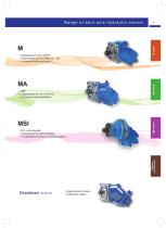
Range of bent axis hydraulic motors ▪ Displacement 5 cc/rev - CETOP ▪ Displacements from 12 to 180 cc/rev - ISO ▪ For fixed and mobile applications ▪ SAE ▪ Displacements from 10 to 180 cc/rev ▪ For fixed and mobile applications Options Accessories ▪ ISO - semi-integrated ▪ Displacements from 28 to 125 cc/rev ▪ For applications mounted on a planetary gearbox ▪ Single direction of rotation ▪ Bi-d
Open the catalog to page 3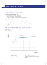
Applications & efficiency ► Main applications Typical applications are those requiring high torque within a small size. The hydraulic motor is essential for rotations where: mechanical solutions are complex or even impossible; electrical or pneumatic power sources are not available; environments are dangerous (i.e. risk of explosion or extreme temperatures). Mowers: drive of grass cutting blade, where mechanical solution would be too complicated or impossible; Blowers: compressor drive; Wheel drive of undercarriages for construction equipment (motor installed on planetary gearbox); Industrial...
Open the catalog to page 4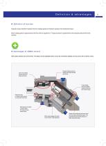
Definition & advantages ► Definition of function Hydraulic motors transform hydraulic flow into rotating speed and hydraulic pressure into mechanical torque. Motor rotating speed is proportional to the flow which is supplied to it. Torque produced is proportional to the hydraulic pressure the motor receives. ► Advantages of LEDUC motors High quality materials and workmanship. The design choices highlighted below ensure the remarkable reliability and long service life of LEDUC motors. No gears between plate and rotating barrel yields reduced noise levels. Choice of increased bearing capacity for...
Open the catalog to page 5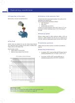
Operating conditions ►Filtration of the hydraulic fluid Before start-up, the motor must be filled with oil. The service life of the motors depends greatly on the quality and the cleanliness of the hydraulic fluid. We recommend minimum cleanliness as follows: NAS 1638 class 9, SAE class 6, ISO/DIS 4406 class 20/18/15. For fluids at very high temperatures 194 to 239 °F (90 to 115 °C), we recommend a minimum cleanliness class of 19/17/14 according to ISO 4406. ►Rotating speeds Minimum rotating speed to obtain continuous rotation is 200 rpm (however, in certain conditions, the motor can run at speeds...
Open the catalog to page 6
Operating conditions ►Direction of rotation The motors rotate clockwise or counter-clockwise depending on the direction of hydraulic flow entering the motor. ►Drain pressure It is essential to drain the motor, T1 or T2, to avoid excessive pressures on the shaft seal. Maximum acceptable internal pressure depends on motor rotating speed. However, following these guidelines will avoid problems during operation: Maximum internal pressure (int P) regardless of rotating speed (continuous): 4 bar; Maximum internal pressure (int P) regardless of rotating speed (peak): 5.5 bar; Minimum pressure in the...
Open the catalog to page 7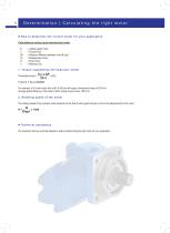
Determination | Calculating the right motor ►How to determine the correct motor for your application Calculations using usual mechanical units: N C ΔP Cy Q η = rotating speed (rpm) = Torque (N.m) = Pressure difference between A and B (bar) = Displacement cc/rev = Flow (l/min) = Efficiency (%) 1. Torque supplied by the hydraulic motor Theoretical torque = For example: a 50 cc/rev motor with a ΔP of 250 bar will supply a theoretical torque of 200 N.m. Average global efficiency of the motor is 90%, actual torque is thus: 180 N.m). 2. Rotating speed of the motor The rotating speed of the hydraulic...
Open the catalog to page 8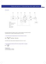
Determination | Calculating the right motor ►Example Hydraulic motor Pressure relief valve Variable displacement pump The receiving organ (winch) ⑥ needs to rotate at N = 400 rpm and supply an actual torque of 200 N.m. The hydraulic pump ② is capable of operating at pressure P up to 350 bar. 1. Calculating the displacement of the hydraulic motor: Cth = Disp. x ΔP thus Disp. = 35.9 cc/rev 20 π In the LEDUC range, choose a motor with a displacement of 32 cc/rev or 41 cc/rev. 2. Calculating the flow Q which the pump needs to supply: Q= Corresponding flow: ▪ For 32 cc/rev motor, Q = 12.8 l/min ▪...
Open the catalog to page 9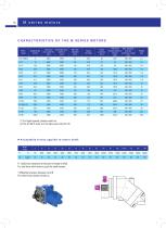
CHARACTERISTICS OF THE M SERIES MOTORS Motor model Continuous Intermittent max. max. speed (1) speed (1) (rpm) (rpm) Displacement (cc/rev) Torque (N.m/bar) Theoretical Max. allowable maximal power at pressure 400 bar continuous / peak (kW) (bar) (1) For higher speeds, please contact us. (2) The M 108 R motor is in the frame size of the M 125. ►Acceptable forces applied to motor shaft Motor model Fr: radial force measured at mid point of length of shaft. Fa: axial force which tends to push the shaft inwards. * Differential pressure between A and B. For other forces, please contact us.
Open the catalog to page 10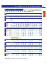
Order code system of M series motors ... To obtain the code for your motor, complete the different parameters 02, 04, 05, 07, 08, 09 and 10 in the table on the left according to the options you require (see table below). 0 = Without suitability for valves 1 = Compatible with flushing valve Drain ports T1 and T2 2 Suitable for use of speed sensor 07
Open the catalog to page 11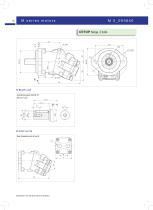
M 5_093840 CETOP flange, 2 bolts ►Shaft end Cylindrical keyed shaft Ø 18 AS 6 x 6 x 32 ►Inlet ports Rear threaded ports A and B G ½" Dimensions in mm are given only as a
Open the catalog to page 12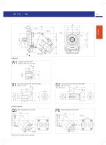
Cylindrical keyed shaft Ø 20 DIN 6885 AS 6 x 6 x 32 +1 6 Cylindrical keyed shaft Ø 25 DIN 6885 AS 8 x 7 x 32 ►Inlet ports Side threaded ports A and B 123.4 Rear threaded ports A and B 143.3 M 22 x 1.5 Dimensions in mm are given only as an indica
Open the catalog to page 13All HYDRO LEDUC catalogs and technical brochures
 AP (L) piston accumulators
6 Pages
 ABVE bladder accumulators
4 Pages
 AS spherical accumulators
4 Pages
 Customized products
8 Pages
 XRT6868 twin flow pump
1 Page
 MT45 series motors
2 Pages
 M series hydraulic motors
16 Pages
 Powerpack GEP 7.3
2 Pages
 PA / PAC series pumps
6 Pages
 TXV series pumps
10 Pages
 Microhydraulics
24 Pages
 Hydropneumatic accumulators
36 Pages
 Piston pumps for trucks
48 Pages


- Hydraulic piston pump
- Compact hydraulic pump
- High-pressure hydraulic pump
- Piston hydraulic motor
- Standard hydraulic pump
- Variable-displacement hydraulic pump
- Industrial accumulator
- Rugged hydraulic pump
- Gear hydraulic motor
- Fixed-displacement hydraulic motor
- High-speed hydraulic pump
- Vehicle hydraulic pump
- Compact hydraulic motor
- High-pressure hydraulic motor
- Double hydraulic pump
- Fixed-displacement hydraulic pump
- Hydraulic screw pump
- Open circuit hydraulic motor