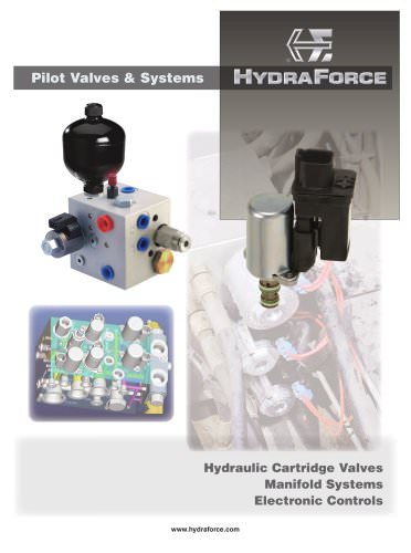
- Catalogs
- HYDRAFORCE
- INTEGR8


INTEGR8

INTEGR8
This technical catalog from HydraForce provides comprehensive information on hydraulic control solutions, including cartridge valves and manifolds. It offers guidelines for the safe and effective selection and use of these products.
The catalog stresses the importance of proper product selection and usage by trained personnel to prevent equipment damage, personal injury, or death. Users are responsible for ensuring the products' suitability and safe application.
The catalog introduces the INTEGR8 concept, which integrates cartridge valves into manifolds for efficient hydraulic control. Users are guided to select components based on function, flow rate, and application needs, with detailed specifications available online.
INTEGR8 offers innovative, efficient, and customizable hydraulic control solutions, emphasizing system efficiency, serviceability, custom capabilities, flexibility, durability, optimal performance, and fewer leak points.
The catalog describes direct-acting flow control circuits, highlighting their use in load-holding and motion control. It details pressure-compensated proportional flow control using SPxx-20x cartridge valves and other components.
Specifications for various solenoid-operated, electro-proportional, directional, and flow control valves are included, with information on operation, features, ratings, and ordering.
HydraForce products come with a five-year limited warranty against defects in material and workmanship. Full warranty details are available in the catalog.
The document provides a technical description of a direct-acting, pressure-compensated hydraulic flow control system, designed to control flow proportionally in response to electrical current changes, using SPxx-20x flow control valve, ECxx-32 pressure compensator, and HCVxx-20 check valve.
The system features a two-way, poppet-type valve available in normally closed (SPxx-20) and normally open (SPxx-21) configurations, with options for manual override and electronic control integration.
In the de-energized state, all ports are blocked. When energized, the system allows flow to the work port (WP), maintaining consistent flow output through a compensator spool.
Performance charts illustrate flow versus pressure and current for various configurations of the SPxx-20 and SPxx-20A valves, demonstrating consistent flow output despite pressure changes.
Recommended applications include conveyor drives, actuator positioning, and lifting functions. A closed-loop current controller is advised for constant current delivery, and SP valves should be paired with a compensator for consistent operation.
Detailed ordering information for different configurations of the SPxx-20 and SPxx-20A valves is provided, including flow ratings and compensator options.
This hydraulic flow control system is optimized for precise metering and repeatable flow output, suitable for various industrial applications requiring reliable hydraulic control.
- Continuous duty unitized, molded coil or weathertight IP69-rated E-coil.
- Various compensation values available.
- Manual override and screen options.
- Cartridge technology for easy servicing.
- Electronic controllers optimized for electro-hydraulic integration.
- Industry common cavities.
- Typical applications include conveyor drives, positioning of horizontal actuators, and control of lifting functions.
- Use a closed-loop current controller to ensure constant current delivery to the coil.
- SP valves are best paired with a compensator for consistent operation.
- Cartridge valve and porting key details are provided for different models.
- Flow vs. pressure and flow vs. current performance charts are included for various models.
- Flow control elements and metering options are detailed for different models.
- Standard and linear metering options are available.
- Efficiency is paramount in hydraulic systems, with load-sensing supporting the delivery of pressurized hydraulic fluid.
- Cartridge valves are customizable for individual applications, reducing cost and size while improving performance.
- Direct-acting directional control valves are used for several machine functions.
- The schematic shows a typical directional control circuit with various components working together.
- Details on how the pressure limiting circuit operates with different components and scenarios.
This document provides detailed technical specifications and operational guidelines for a series of hydraulic valves, specifically the SPxx-47C and SPxx-47D models, used in controlling flow in hydraulic systems.
- The SPxx-47C and SPxx-47D valves operate at a pressure of up to 241 bar/3500 psi and 240 bar/3500 psi respectively.
- Flow ratings vary based on spring size, with the SP08-47C handling up to 21.6 lpm (5.7 gpm) and the SP08-47D up to 24.6 lpm (6.5 gpm).
- Hysteresis is less than 7%, and the coil duty rating allows continuous operation up to 115% of nominal voltage.
- Oil viscosity recommended is 32 cSt/150 sus at 40°C (104°F).
- In the neutral position, the SPxx-47C blocks oil at all ports, while the SPxx-47D connects ports A and B to the tank to prevent cavitation.
- When energized, flow is directed from port P to either work port A or B, depending on which coil (S1 or S2) is powered.
- The ECxx-32 component ensures a constant pressure drop across the metering spool, maintaining consistent flow regardless of load conditions.
- Port reliefs (RV08-20) protect against sudden shock loads.
- Anti-cavitation check valves (CV08-20) ensure the cylinder remains filled with oil.
- Load sense check valves (HCV06-20) allow multiple work sections to be connected in parallel.
- Cartridges are voltage interchangeable and easy to service, with efficient wet-armature construction.
- For cylinder applications, connect the base end to work port B.
- SP Series valves should not be used as primary load-holding valves; use counterbalance or dual-pilot-operated check valves if load-holding is required.
- Mount the valve below the reservoir oil level to prevent air instability, or use a check valve at the manifold outlet.
- Use a closed-loop current controller to maintain constant current delivery to the coil.
This document provides a detailed technical analysis of hydraulic control systems, focusing on the use of PE16-S67C and PE16-S67D directional control valves in load-sensing applications.
The PE16-S67C and PE16-S67D are three-position, four-way proportional valves used in closed center, pressure-compensated load-sensing circuits.
The directional control circuit consists of a PE16-S67C valve, an EC16-32 flow regulator/pressure compensator, and two EHPR98-T35 reducing/relieving valves.
- Minimize back pressure at port D when using an EHPR valve to ensure full valve shifting.
- Match pilot pressures to the PE spool requirements to avoid excessive deadband.
- Use pilot-operated check valves or counterbalance valves for low work port leakage applications.
- Optimal control signal is 100 Hz PWM at maximum dither level.
- Ideal for double-acting cylinder and motor applications.
- Continuous duty unitized, molded coil or weather-tight IP69-rated E-coil.
- Hardened parts for long life and efficient wet-armature construction.
- Cartridges are voltage interchangeable and easy to service.
- Operating Pressure: 240 bar/3500 psi.
- Flow Rating: Up to 83.4 lpm/22 gpm for PE16-S67C and 77.7 lpm/20.5 gpm for PE16-S67D.
- Hysteresis: Less than 7%.
- Coil Duty Rating: Continuous up to 115% of nominal voltage.
This document serves as a comprehensive guide for selecting and applying PE16-S67C and PE16-S67D valves in hydraulic systems, providing essential specifications, operational theory, and application tips to ensure optimal performance.
This document provides technical specifications, performance data, and application guidelines for HydraForce hydraulic valves, specifically the PE12-S67D, PE12-S67H, and PE16-S67H models.
Catalog excerpts
FIVE-YEAR LIMITED WARRANTY All HydraForce products carry a five-year limited warranty against defects in material and workmanship. For full warranty information see page the last page of this catalog.
Open the catalog to page 2
A Word About Safety WARNING READ THIS DOCUMENT BEFORE INSTALLING OR USING HYDRAFORCE PRODUCTS. IMPROPER SELECTION, IMPROPER USE, USE BY ANYONE OTHER THAN TRAINED USERS HAVING APPROPRIATE TECHNICAL AND MECHANICAL EXPERTISE, OR FAILURE OF HYDRAFORCE PRODUCTS OR RELATED ITEMS RESULTING THEREFROM CAN CAUSE DAMAGE TO EQUIPMENT OR PROPERTY, SERIOUS PERSONAL INJURY, OR DEATH. This document and other information from HydraForce, its subsidiaries and authorized distributors (collectively “HydraForce”) together only provide product installation guidelines and product or system usage options, each of which...
Open the catalog to page 3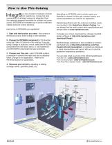
is a new concept in hydraulic controls from HydraForce. It takes the best combination of cartridge valves and integrates them into optimally designed manifolds for cylinder and motor control. INTEGR8 is the fastest way to arrive at efficient, reliable hydraulic control solutions. Here's how to INTEGR8 your application: 1. Start with the function you need - flow control or directional control, direct-acting or pilot-operated. 2. Choose the INTEGR8 component for the function, using the Table of Contents in this catalog. If you are using i-Design to build your circuit, select the INTEGR8 component...
Open the catalog to page 4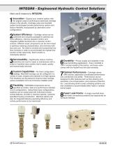
INTEGR8 - Engineered Hydraulic Control Solutions Here are 8 reasons to INTEGR8: Innovation - Expand your creative options with the largest range of performance-optimized cartridge valves in the industry. Cartridge valve and manifold system technologies provide performance options and feature flexibility unsurpassed by alternative valve configurations. System Efficiency - Cartridge valves can be combined and uniquely packaged to optimize machine efficiency, improve operator control, and integrate multiple functions into a common control scheme. Different-sized components can be inter-mixed to...
Open the catalog to page 5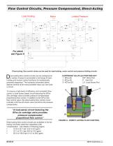
Flow Control Circuits, Pressure Compensated, Direct-Acting Direct-acting, flow control valves can be used for load-holding, motor control and pressure limiting circuits. irect-acting flow control circuits can be configured in a variety of ways to accomplish a full range of loadholding and motion control functions for hydraulically powered equipment. The hydraulic schematic above depicts several of the many possible ways you can build a circuit. To ensure a high-level of efficiency and consistent flow control, a load-sense based circuit featuring the SPxx20x cartridge valve provides pressure-compensated...
Open the catalog to page 6
Theory of Operation - Direct-Acting Flow Control For simplicity, the load hold valve downstream of the work port (WP) has been omitted. In Figure A - DIRECTACTING FLOW CONTROL, all products are shown at rest and with no pressure applied to the inlet. Schematic showing flow control WP In Figure B - DE-ENERGIZED, the pump is on and system pressure is fed to the inlet of the flow control valve. The compensator closes to block the flow of oil to the SP flow control. When the solenoid coil is energized (Figure C ENERGIZED), oil is allowed to flow to the work port. The control pressure drop sensed...
Open the catalog to page 7
Direct-Acting, Pressure Compensated, Normally Closed DESCRIPTION A combination of valves working together to provide optimal control of hydraulically powered functions. This direct-acting, pressure-compensated product controls flow proportionally in response to a change in current. Valves in circuit include: SPxx-20x flow control valve ECxx-32 pressure compensator HCVxx-20 check valve For applications requiring low work port leakage, the use of a pilot-operated check valve or counter balance valve is suggested. CARTRIDGE VALVE and PORTING KEY 1 2 3 WP Work Port LS Load Sense Port P Inlet Port...
Open the catalog to page 8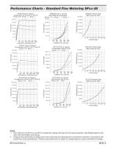
Performance Charts - Standard Fine Metering SPxx-20 SP08-20 Flow vs. Pressure Compensation with EC08-32 @ 1200 mA 250 psi —— 150 psi 80 psi SP08-20 Flow vs. Current with EC08-32 Compensator 80 psi 250 psi —— 150 psi 18.9/5.0 PRESSURE bar/psi FLOW lpm/gpm FLOW lpm/gpm SP08-20 Pressure Drop With Current at 100% FLOW lpm/gpm DIFFERENTIAL PRESSURE bar/psi SP10-20 Flow vs. Pressure Compensation with EC12-32 @ 1200 mA 220 psi —— 80 psi SP10-20 Flow vs. Current Compensation with EC12-32 220 psi —— 80 psi PRESSURE bar/psi FLOW lpm/gpm FLOW lpm/gpm SP10-20 Pressure Drop With Current at 100% SP12-20 Flow...
Open the catalog to page 9
Performance Charts - Linear Metering Option SPxx-20A SP08-20A Flow vs. Pressure Compensation with EC08-32 @ 1200 mA 250 psi —— 150 psi 80 psi SP08-20A Flow vs. Current with EC08-32 Compensator 250 psi —— 150 psi 80 psi SP08-20A Pressure Drop With Current at 100% 45.5/650 PRESSURE bar/psi FLOW lpm/gpm FLOW lpm/gpm DIFFERENTIAL PRESSURE bar/psi SP10-20A Flow vs. Current Compensation with EC12-32 220 psi —— 80 psi PRESSURE bar/psi FLOW lpm/gpm SP10-20A Pressure Drop With Current at 100% FLOW lpm/gpm DIFFERENTIAL PRESSURE bar/psi SP12-20A Flow vs. Current with EC16-32 Compensator 200 psi —— 80 psi...
Open the catalog to page 10
Ordering Information - SPxx-20 and SPxx-20A Metering Options Flow vs. current performance for standard fine and linear metering is charted on the adjacent graph. To specify the Linear Metering Option, add an "A" to the valve model code. See the To Order section. FLOW lpm/gpm (Increasing) HydraForce offers a choice of two metering options on its SPxx-20 cartridge valves. The standard metering option provides fine metering for smooth control. For applications that require extra flow capacity rather than fine metering, a linear metering option is available. TO ORDER To order, refer to ordering information...
Open the catalog to page 11
Direct-Acting, Pressure Compensated, Normally Open DESCRIPTION A combination of valves working together to provide optimal control of hydraulically powered functions. This direct-acting, pressure-compensated product controls flow proportionally in response to a change in current. Valves in circuit include: SPxx-21x flow control valve ECxx-32 pressure compensator HCVxx-20 check valve For applications requiring low work port leakage, the use of a pilot-operated check valve or counter balance valve is suggested. CARTRIDGE VALVE and PORTING KEY 1 2 3 WP Work Port LS Load Sense Port P Inlet Port APPLICATION...
Open the catalog to page 12All HYDRAFORCE catalogs and technical brochures
 INTEGR8
4 Pages
 H-Series High Pressure Valves
12 Pages
 HTD10-40
4 Pages
 Full Line Products Guide
28 Pages
 Material Handling Solutions
4 Pages
 Wheel Loaders
8 Pages
 Harvesting
8 Pages
 Excavators
8 Pages
 Tractors
8 Pages
 2-002
2-0021 Page
 Directional Sandwich Valves
4 Pages