
- Catalogs
- HYDRAFORCE
- 2-002


2-002

2-002
SP valves rely on the current in the coil for performance, which is influenced by the applied voltage and coil resistance. Voltage increases raise current levels, while resistance increases lower them. In mobile equipment, voltage varies around the nominal battery voltage, affecting coil performance. As coil temperature rises, resistance increases, reducing current and valve output. A closed-loop current controller is recommended to maintain constant current despite resistance changes.
Voltage and Temperature Considerations
To ensure maximum flow at high temperatures, it's crucial to know the actual voltage applied to the coil, including any voltage drop across the controller. On engine-driven equipment, a coil rated at nominal voltage is suitable, while battery-operated equipment benefits from a coil rated below nominal voltage. The current applied to SP valves varies, stabilizing around an average value defined as I-Average = (I-Threshold + I-Maximum) ÷ 2.
Graphical Analysis
Graphs illustrate the operating range of HydraForce standard coils on SP valves, showing the voltage needed to maintain average current. For example, at 20°C, an 08 size 10 VDC coil requires 83% of nominal voltage for maximum current, while at 80°C, 102% is needed. A 12 VDC coil requires 102% at 20°C, exceeding the maximum 115% at 80°C, indicating unsuitability for high temperatures.
Coil Electrical Rating
The document provides electrical ratings for different valve sizes and coil voltages, specifying maximum control currents:
- 08 size, 10 VDC: 1170 ±115 mA
- 08 size, 12 VDC: 1000 ±100 mA
- 10 size, 10 VDC: 1320 ±120 mA
- 10 size, 12 VDC: 1100 ±100 mA
Conclusion
Understanding the relationship between voltage, temperature, and coil resistance is essential for optimizing SP valve performance. The use of closed-loop current controllers and appropriate coil ratings based on equipment type and operating conditions is recommended for effective operation.
Catalog excerpts
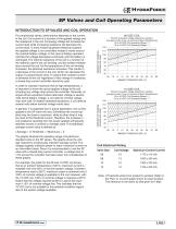
SP Valves and Coil Operating Parameters INTRODUCTION TO SP VALVES AND COIL OPERATION In order to maintain maximum flow at high temperatures, it is important to know the actual applied voltage to the coil including any voltage drop across the controller. Generally, on engine-driven equipment where alternator voltage is several volts above battery voltage, a coil rated at nominal voltage may work well. On battery-operated equipment, a coil rated at several volts below nominal voltage works best. In general, it is expected that in actual application, the current applied to the SP valve will vary. Sometimes the current applied may be close to maximum, while at other times it may be close to the threshold current. Therefore, the increase in coil resistance resulting from the power applied will typically stabilize around a nominal or average value. This stabilized, average current value is defined as: PERCENT OF NOMINAL SYSTEM VOLTAGE For example, the graph for the 08 size 10 VDC coil shows that at an ambient temperature of 20°C, maximum current is available with only 83% of nominal system voltage. If ambient temperature rises to 80°C, maximum output is achieved only if 102% of nominal voltage is available to the coil. However, with the 12 VDC coil, 102% of nominal voltage is required at 20°C. Notice that the voltage required at 80°C is above the maximum 115% of nominal voltage line. This indicates that the 12 VDC coil is not suitable for this ambient condition regardless of the system voltage available. Percent of system voltage required to maintain average current (I-ave.) at various ambient temperatures 10 or 20 VDC Coil Operating Range: \ \ \ 12 or 24 VDC Coil Operating Range: / / / I-Average = (I-Threshold + I-Maximum) ÷ 2 The graphs illustrate the operating range of HydraForce standard coils on the SP valves. The graphs show the voltage required to continuously maintain average current. The voltage supplies sufficient power to reach maximum current on an intermittent basis. Since it is recommended to use the SP valve with a closed-loop current controller, a voltage drop of 1.5V across the controller has been taken into consideration in these graphs. Percent of system voltage required to maintain average current (I-ave.) at various ambient temperatures 10 or 20 VDC Coil Operating Range: \ \ \ 12 or 24 VDC Coil Operating Range: / / / PERCENT OF NOMINAL SYSTEM VOLTAGE For proportional valves, performance depends on the current in the coil. Coil current is a function of the applied voltage and the resistance in the coil. Increasing voltage will increase the current level while increasing resistance will decrease the current level. In most mobile equipment electrical systems the applied voltage is not controlled; instead it varies around the nominal battery voltage. In the case of battery-operated vehicles the voltage decreases continually until the battery is recharged. The internal resistance of the coil is a function of the material used in the coil winding, and the ambient temperature around the coil. As the temperature of the coil winding increases, the electrical resistance increases. This results in a decrease of the current in the coil, which can decrease the output of a proportional valve. To assure that constant current is delivered to the coil regardless of this change in resistance, a closed-loop current controller should be used. Coil Electrical Rating Valve Size Coil Voltage Maximum Control Current Note: I-Threshold varies from product to product. Refer to the Flow vs. Current graph shown for each product. The tolerance is the same as that given for I-Max.
Open the catalog to page 1All HYDRAFORCE catalogs and technical brochures
 INTEGR8
4 Pages
 H-Series High Pressure Valves
12 Pages
 INTEGR8
36 Pages
 HTD10-40
4 Pages
 Full Line Products Guide
28 Pages
 Material Handling Solutions
4 Pages
 Wheel Loaders
8 Pages
 Harvesting
8 Pages
 Excavators
8 Pages
 Tractors
8 Pages
 Directional Sandwich Valves
4 Pages


Archived catalogs

- Control valve
- Threaded valve
- Electrically operated valve
- Regulating valve
- On/off valve
- Flap valve
- Check valve
- Electric valve
- ISO valve
- 2-way solenoid valve
- NC solenoid valve
- Direct-operated solenoid valve
- Metal solenoid valve
- Valve for industrial applications
- Steel valve
- Metal check valve
- Hydraulic valve
- 2-channel valve
- Compact valve