- Catalogs
- HUSKY INJECTION MOLDING SYSTEMS
- Gate Insert Manufacturing and Inspection
Gate Insert Manufacturing and Inspection
1 /6Pages

Gate Insert Manufacturing and Inspection
1 /6Pages
Catalog excerpts

HUSKY Keeping our customers in the lead Original Instructions
Open the catalog to page 1
Gate Insert Manufacturing and Inspection This product manual is intended to provide information for safe operation and/or maintenance. Husky reserves the right to make changes to products in an effort to continually improve the product features and/or performance. These changes may result in different and/or additional safety measures that are communicated to customers through bulletins as changes occur. This document contains information which is the exclusive property of Husky Injection Molding Systems Limited. Except for any rights expressly granted by contract, no further publication or commercial...
Open the catalog to page 2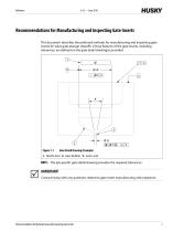
Recommendations for Manufacturing and Inspecting Gate Inserts This document describes the preferred methods for manufacturing and inspecting gate inserts for valve gate plunger shutoffs. Critical features of the gate inserts, including tolerances, are defined on the gate detail drawing(s) provided. 1 Gate Detail Drawing (Example) 1. Nozzle Seal 2. Gate Bubble 3. Gate Land NOTE: The job specific gate detail drawing provides the required tolerances. IMPORTANT! Contact Husky with any questions related to gate insert manufacturing and inspection. Recommendations for Manufacturing and Inspecting Gate...
Open the catalog to page 3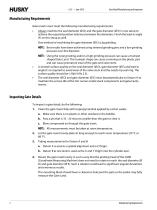
Gate Detail Manufacturing and Inspection Manufacturing Requirements Gate inserts must meet the following manufacturing requirements: • Always machine the seal diameter (Ø D) and the gate diameter (Ø E) in one setup to achieve the required position tolerance between the diameters. Finish the lead-in angle (F) on this setup as well. One method of machining the gate diameter (Ø E) is jig grinding. NOTE: Best results have been achieved using sintered grinding pins and a low grinding pressure over this diameter. NOTE: Using the wrong tooling and/or a high grinding pressure can cause a trumpet • •...
Open the catalog to page 4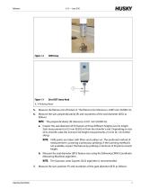
Zeiss VAST Sensor Head Measure the flatness (G) of Datum A. The flatness (G) tolerance is 0.005 mm (0.0002 in). Measure the size, perpendicularity (R) and roundness of the seal diameter (Ø D) as follows: NOTE: The perpendicularity (R) tolerance is 0.01 mm (0.0004 in). a. Inspect the seal diameter (Ø D) feature at three different heights over its length. Start measurement at 0.5 mm (0.002 in) from the chamfer’s end. Depending on size of its chamfer, take the 2nd and 3rd height measurements 2.5 mm (0.1 in) further along. NOTE: 1000 points are taken with filters and outliers on. The preferred method...
Open the catalog to page 5
Gate Detail Manufacturing and Inspection NOTE: The position (P) tolerance is 0.01 mm (0.0004 in) at the maximum material condition. a. Measure the insert prior to inspection with a height gage. The distance from the top of the insert (Datum A) to the bottom of the gate. This is to ensure the CMM probe goes deep enough and can measure very close to the “sharp” or end of the gate. b. Take measurements every 0.050mm (0.002in) starting at 0.005mm (0.0002in) above the "sharp" feature to 0.200mm (0.008in) past the Gate Land into the gate. Example: For a typical 0.400mm (0.016in) Gate Land length, take...
Open the catalog to page 6All HUSKY INJECTION MOLDING SYSTEMS catalogs and technical brochures
 Altanium Neo5
182 Pages
 Schöttli® Medical Molds
16 Pages
 UltraSync-E Technology
2 Pages
 UNIFY™
2 Pages
 Shotscope NX
2 Pages
 H-PET AE System
4 Pages
 ultra helix valve gate
4 Pages
 Pro-Act Program
4 Pages
 PowerPro G
2 Pages
 Altanium Servo Control
4 Pages
 Ultra SideGate
2 Pages
 Ultra Helix TM Valve Gate
2 Pages
 Ultra 350 Nozzles
2 Pages
 Ultra 1000 Nozzles
2 Pages
 Ultra 250 Nozzles
2 Pages
 Express conversion Programs
2 Pages
 Encore program
4 Pages
 Ultra SideGate
2 Pages
 UNIFY
UNIFY2 Pages
 Top Entry Robots
2 Pages
 Specialty Closures
2 Pages
 ShotscopeNX
2 Pages
 PRONTO Hot Runners
4 Pages
 ProAct Program
4 Pages
 Machine Audits
2 Pages
 HyPET Recycled Flake
2 Pages
 HyPET Preform Systems
4 Pages
 Ultra Valve Gate Technology
4 Pages
 H-MED AE
2 Pages
 Altanium Neo2
2 Pages


Archived catalogs
 Hylectric Machines
4 Pages
 HyCAP Beverage Closures
4 Pages
 Thinwall Packaging
4 Pages
 Company Overview
26 Pages
 Altanium Delta3
2 Pages


- AMOT digital temperature control
- Liquid nozzle
- AMOT temperature controller
- AMOT injection molding machine
- AMOT digital temperature controller
- AMOT horizontal injection molding machine
- AMOT hydraulic injection molding machine
- AMOT air nozzle
- Industrial tip
- AMOT electric injection molding machine
- Plastic injection mold
- Injection nozzle
- Industrial temperature controller
- Compressed air nozzle
- Process temperature controller
- Multi-cavity plastic injection mold
- Hot runner nozzle
- Plastic injection mold for the packaging industry
- Hot-runner plastic injection mold
- Packaging plastic injection mold